Apparatus for optical communication for elevator

A communication device and optical communication technology, applied in the directions of transportation, packaging, elevators, etc., can solve the problems of serious transmitter surface, long cable length, interference with optical communication, etc. Effects of foreign objects interfering with communication and preventing dust accumulation

Active Publication Date: 2016-03-02
尹一植 +1
View PDF10 Cites 0 Cited by
  • Summary
  • Abstract
  • Description
  • Claims
  • Application Information

AI Technical Summary

Problems solved by technology

In particular, the elevator shaft moves very frequently due to the lifting and lowering of the elevator, and there are a lot of foreign matter such as dust, and the surface of the transmitter is covered with foreign matter to a great extent.
In this case, optical communication is interfered and data transmission cannot be performed correctly
[0005] And, as shown in the figure, it is necessary to connect the controller C and the optical communication transmitter 140 by a wired cable. The controller C includes a computer located in a machine room at the upper end of the elevator shaft, so the length of the wired cable is very long. There will be some problems in terms of maintenance management and costs

Method used


Image

  • Apparatus for optical communication for elevator
  • Apparatus for optical communication for elevator
  • Apparatus for optical communication for elevator

Examples


Embodiment Construction

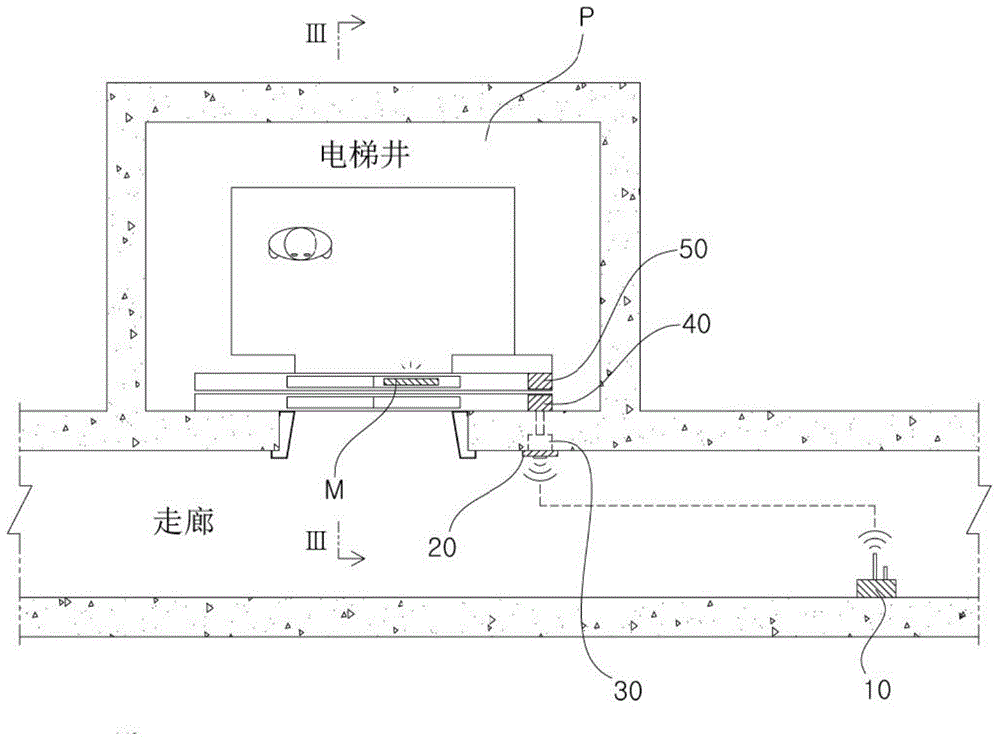
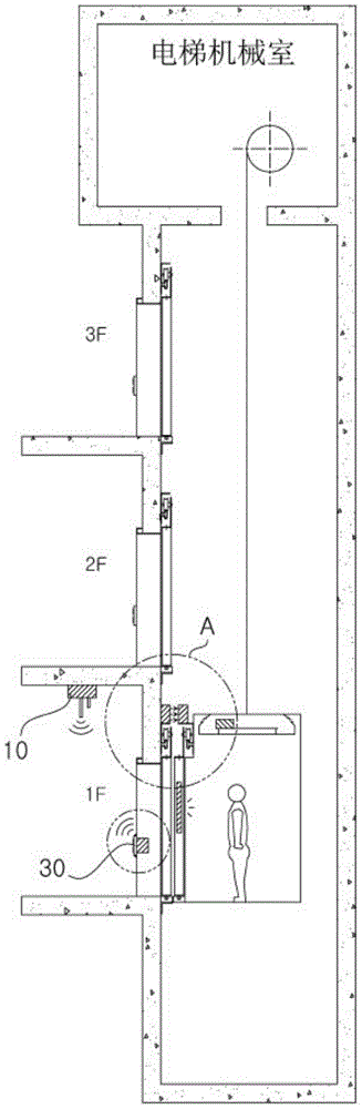
[0031] figure 2 is a plan view of an example of the present invention, image 3 yes figure 2 Sectional view of line III-III, image 3 A is image 3 Enlarged view of part A of .

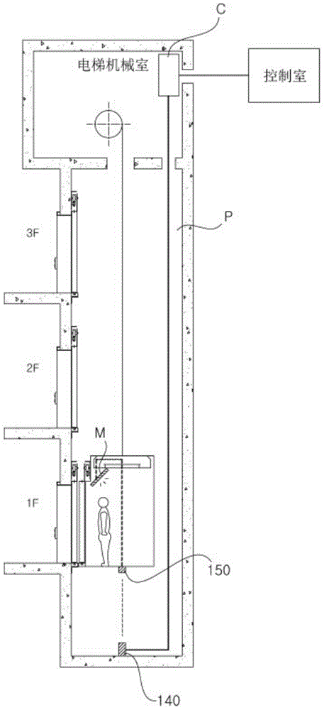
[0032] As shown in the figure, different from the traditional way, a data transmitter 10 is arranged on the wall or ceiling of the front lobby (corridor) of the elevator shaft. For example, if figure 2 As shown, the wall surface in front of the elevator door on the 1st floor, or as image 3 A data transmitter 10 is provided on the ceiling of the lobby (corridor) on the first floor. The data transmitter 10 transmits data, especially digital data, by any existing means including LTE, WiFi or wireless LAN.

[0033] The hall button cover 20 is arranged next to the elevator door, which is used to select the required floor or lift. The data receiver 30 is arranged behind this hall button cover 20, and the data receiver is connected with the data transmitter 10 wirelessly. Receive digital data. P...


PUM


Abstract

The present invention relates to an apparatus for optical communication for an elevator, the apparatus reducing the optical communication distance to the shortest distance and comprising: a data transmitter installed on the wall or ceiling of the hall in front of an elevator shaft; a data receiver installed behind a hall button cover of a building elevator and connected wirelessly to the data transmitter to receive digital data therefrom; an antenna built into the hall button cover and connected to the a data receiver; an optical communication transmitter, connected by wire to the a data receiver and installed on the wall of the elevator shaft, for converting digital data to optical data and transmitting the latter; an optical communication receiver, installed in the elevator at a location facing the optical communication transmitter when the elevator is stopped to allow passengers to get in and out, for receiving data the optical communication transmitter by means of wireless optical communication; a controller, connected by wire to the optical communication receiver and a control room and installed in the ceiling of the elevator, for receiving data from the optical communication receiver to convert into image data, and being controlled by the control room; and a monitor, connected by wire to the controller and installed on the door, wall or ceiling of the elevator, for receiving and displaying image data from the controller.

Description

technical field [0001] The present invention relates to an optical communication device for an elevator, more specifically, an optical communication device for an elevator that shortens the optical communication distance to the shortest distance. Background technique [0002] As there are more and more examples of installing displays for displaying information on ceilings such as doors and walls inside elevators, there are also increasing cases where optical communication is selected to transmit data from the outside to the displays. [0003] figure 1 It is a cross-sectional view of an elevator shaft showing this optical communication method. For optical communication, an optical communication transmitter 140 is generally installed on the bottom of the elevator shaft, and an optical communication receiver 150 is installed on the bottom of the elevator E opposite to the optical communication transmitter. In this case, generally, when the elevator E reaches the lowest point ...

Claims


Application Information

Patent Timeline
Patent Type & Authority Applications(China)
IPC IPC(8): B66B3/02B66B3/00
CPCB66B3/00B66B3/02
Inventor 尹一植尹準儧
Owner 尹一植
Why Eureka
Try Eureka