Cleaning device

A cleaning device and a technology to be cleaned are applied in the field of copper ball cleaning devices for electroplating and cleaning devices, which can solve the problems of poor cleaning effect, high manual labor intensity, and low cleaning efficiency, and achieve easy maintenance, good support effect, and machine durable effect

Active Publication Date: 2016-03-02
NEW FOUNDER HLDG DEV LLC +1
View PDF6 Cites 1 Cited by
  • Summary
  • Abstract
  • Description
  • Claims
  • Application Information

AI Technical Summary

Problems solved by technology

[0004] Therefore, the technical problem to be solved by the present invention is to overcome the defects of high manual labor intensity, poor cleaning effect and low cleaning efficiency caused by

Method used


Image

  • Cleaning device
  • Cleaning device
  • Cleaning device

Examples


Embodiment 1

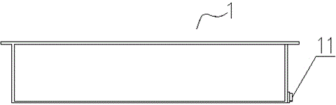
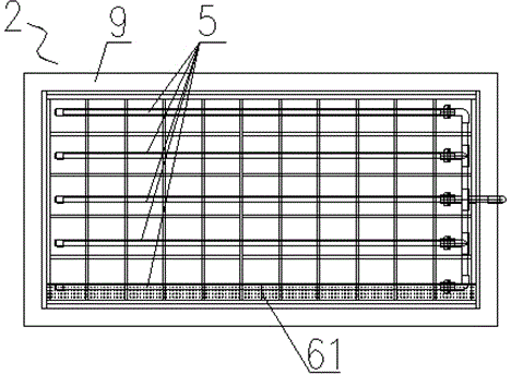
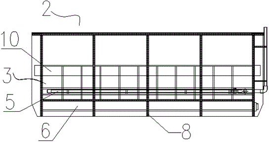
[0059] This embodiment provides a cleaning device, taking the cleaning of copper balls for electroplating as an example, and referring to the attached Figure 1-6 Shown in detail.

[0060] Such as Figure 1-4 As shown, the above-mentioned cleaning device includes a cleaning container 2, and also includes a dividing device that carries the parts to be cleaned and divides the inner cavity of the cleaning container 2 into an upper space 21 and a lower space 22, and a drum is arranged in the lower space 22. The wind device 4 is provided on the partition device to introduce the air bubbles generated by the blower device 4 from the lower space 22 into the upper space 21 to push the cleaning liquid to flush when cleaning the piece to be cleaned. The communication part of the article to be cleaned.

[0061] The above-mentioned technical solution is the core technical solution of the present invention. When the above-mentioned cleaning device is used to clean the copper balls for ele...


PUM


Abstract

The invention provides a cleaning device. The cleaning device comprises a cleaning container and further comprises a dividing device which bears an article to be cleaned and divides an inner cavity of the cleaning container into upper space and lower space. A blower device is arranged in the lower space. The dividing device is provided with a communicating part for leading bubbles generated by the blower device into the upper space from the lower space so as to push cleaning liquid to scour the article to be cleaned when the article to be cleaned is cleaned. When the cleaning device is used for cleaning the article to be cleaned, only the article to be cleaned needs to be placed in the upper space, the blower device is started, the bubbles generated by the blower device enter the upper space from the lower space through the communicating part, and the cleaning fluid is pushed to scour the article to be cleaned; and accordingly, impurities, dirt and the like attached to the article to be cleaned are scoured down, and the cleaning function of the article to be cleaned is achieved accordingly.

Description

technical field [0001] The invention relates to a cleaning device, in particular to a cleaning device for cleaning copper balls for electroplating, and belongs to the technical field of cleaning devices for copper balls for electroplating. Background technique [0002] In the field of PCB board manufacturing technology, the hole copper and surface copper on the PCB are mainly realized by electroplating copper or sinking copper. When electroplating copper for hole copper and surface copper, the rectifier current is connected to the anode (+) titanium basket of the copper cylinder through the rectifier line, and the cathode (-) is connected to the PCB substrate through the fixture, controlled by adjusting the current density and plating time Copper plating layer thickness of hole copper and surface copper. After a certain period of electroplating production consumption, the copper balls contained in the above-mentioned titanium basket will gradually become smaller or become c...

Claims


Application Information

Patent Timeline
IPC IPC(8): C23G3/00
Inventor 黄志强
Owner NEW FOUNDER HLDG DEV LLC
Why Eureka
Try Eureka