
Rolling bearing integrated with permanent support suitable for jack-up construction

A technology of permanent support and jacking method, which is applied in the erection/assembly of bridges, bridges, buildings, etc. It can solve the problems of large influence of flexible piers, adverse effects of bridge piers, complex device structure, etc., and achieve low cost and simplified construction operation process , the effect of reasonable structural design

Inactive Publication Date: 2016-11-30
TIANJIN CHENGJIAN UNIV
View PDF7 Cites 0 Cited by
  • Summary
  • Abstract
  • Description
  • Claims
  • Application Information

AI Technical Summary

Problems solved by technology

When using temporary sliding support to push, after the main beam is pushed into place, it is necessary to use a jack to lift the main beam, then remove the slideway and the concrete pad at the base of the slideway, and then install the formal support. The disadvantage of this construction process is that complex
Although the construction process can be simplified by using the sliding support integrated with the permanent support, the structure of this device is complex and the cost is high. Therefore, temporary sliding supports are often used in the construction of the pushing method in my country
In addition, sliding friction is generated in the above two support systems, which is relatively large compared with rolling friction
Because the horizontal force generated by friction will cause the horizontal displacement of the pier, it will have an adverse effect on the pier, especially on the flexible pier.

Method used


Image

  • Rolling bearing integrated with permanent support suitable for jack-up construction
  • Rolling bearing integrated with permanent support suitable for jack-up construction
  • Rolling bearing integrated with permanent support suitable for jack-up construction

Examples


Embodiment Construction

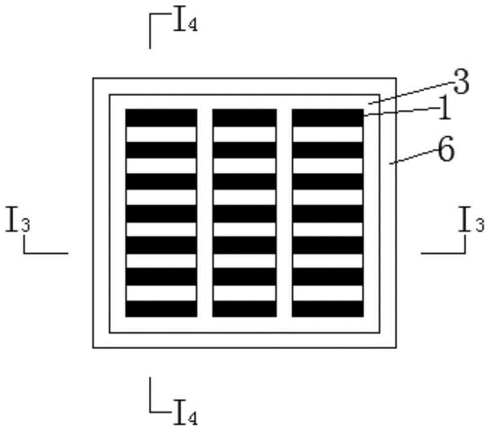
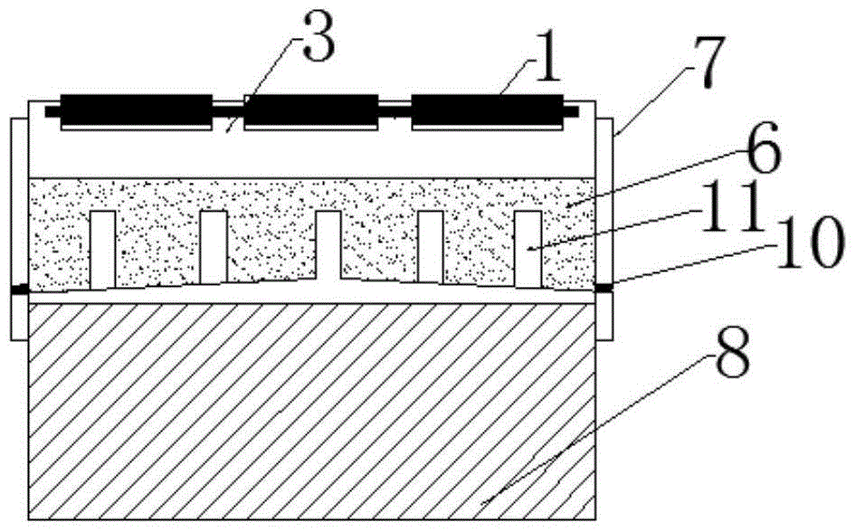
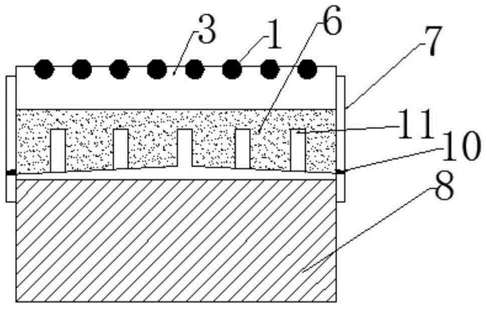
[0012] The rolling bearing integrated with the permanent support suitable for the jacking method construction provided by the present invention will be described in detail below in conjunction with the accompanying drawings and specific embodiments.

[0013] Such as figure 1 — image 3 As shown, the rolling bearing integrated with the permanent support suitable for the jacking method construction provided by the present invention includes a plurality of cast steel rollers 1, standard sand 6, a slide plate 3, a casing 7, a common support 8, and a plurality of screws 10 and a plurality of steel columns 11; wherein the shell 7 is a box structure with an opening formed on the upper end, and the lower end is fixed on the upper end of the common support 8, and at least one screw hole is formed at the lower part of each side, and is blocked by a screw 10 The screw hole is equipped with standard sand 6 inside; the lower ends of multiple steel columns 11 are fixed on the bottom surfac...


PUM


Abstract

The invention provides a rolling bearing suitable for construction by an incremental launching method and integrated with a permanent support. The rolling bearing comprises a plurality of cast steel rollers, standard sand, a sliding plate, a shell, a common support, a plurality of screws and a plurality of steel columns, wherein the shell is a box body structure; an opening is formed in the upper end of the box body structure; the lower end of the box body structure is fixed at the upper end of the common support; at least one screw hole is formed in the lower part of each side surface of the box body structure; the screw holes are blocked by screws; the box body structure is filled with the standard sand; the lower ends of the steel columns are fixed on the bottom surface of the shell at equal intervals; the sliding plate is placed at the surface of the standard sand in the shell; and the cast steel rollers are divided into a plurality of rows and are arranged at the surface of the sliding plate side by side. By the rolling bearing suitable for construction by the incremental launching method and integrated with the permanent support, the friction force generated in an incremental launching process can be reduced, so that horizontal displacement of a pier is reduced. In addition, the rolling bearing is reasonable and simple in structural design, low in cost and convenient to use, therefore, a construction operation technology can be simplified, and labor and time are saved.

Description

technical field [0001] The invention belongs to the technical field of bridge design and construction, and in particular relates to a rolling support integrated with a permanent support suitable for construction by the jacking method. Background technique [0002] The jacking method is mostly used in the construction of prestressed reinforced concrete equal-section continuous beam bridges and cable-stayed bridges. It refers to the temporary sliding of the beam body through the top of each pier when the beam body is poured or assembled segment by segment at the bridge head and pushed longitudinally by a jack. The construction method of the bearing surface in place. In the jacking method construction, the support system is divided into temporary sliding bearings and sliding bearings integrated with permanent bearings. When using temporary sliding support to push, after the main beam is pushed into place, it is necessary to use a jack to lift the main beam, then remove the sli...

Claims


Application Information

Patent Timeline
Patent Type & Authority Patents(China)
IPC IPC(8): E01D21/06
CPCE01D21/06
Inventor 李自林薛江刘鹏吴煜哲
Owner TIANJIN CHENGJIAN UNIV
Features
  • Generate Ideas
  • Intellectual Property
  • Life Sciences
  • Materials
  • Tech Scout
  • Unparalleled Data Quality
  • Higher Quality Content
  • 60% Fewer Hallucinations
Learn More