Supercharge Your Innovation With Domain-Expert AI Agents!

Segmented type deflecting screw drill for horizontal drilling

A technology for horizontal drilling and screw drilling tools, applied in drilling equipment, earth-moving drilling, impact drilling, etc., can solve problems such as damage to the drill bit motor assembly, complicated processing and manufacturing of elastic casings, and reduced drilling efficiency, and achieve smooth sliding. Effect

Active Publication Date: 2016-03-02
YANCHENG XINYONGJIA PETROLEUM MACHINERY MFG
View PDF7 Cites 1 Cited by
  • Summary
  • Abstract
  • Description
  • Claims
  • Application Information

AI Technical Summary

Problems solved by technology

[0002] In horizontal drilling, deflection needs to be performed while drilling. The existing deflection pipeline is mainly composed of an elastic shell and a flexible drill pipe with an inner sleeve. The elastic shell needs to be transported and assembled before drilling and deflection can be performed; The elastic shell has an elastic bending structure, and the processing and manufacturing are relatively complicated; when the drilling environment is relatively narrow, the deflection efficiency of the existing deflection pipeline is relatively slow; and due to the complex geological environment, it is inevitable to encounter relatively hard rock formations , if the same power is maintained for continuous operation, it may cause damage to the drill bit or even the motor assembly, which not only increases the drilling cost, but also reduces the drilling efficiency

Method used


Image

  • Segmented type deflecting screw drill for horizontal drilling
  • Segmented type deflecting screw drill for horizontal drilling
  • Segmented type deflecting screw drill for horizontal drilling

Examples


Embodiment Construction

[0036] The technical solutions provided by the present invention will be described in detail below in conjunction with specific examples. It should be understood that the following specific embodiments are only used to illustrate the present invention and are not intended to limit the scope of the present invention.

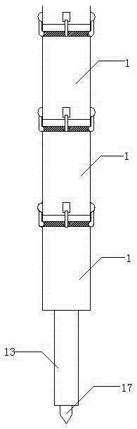
[0037] Such as figure 1 Shown is the horizontal section of the present invention picture , the present invention is a Segmented deflecting screw drilling tool for horizontal drilling , consisting of whipstock and drilling sections,

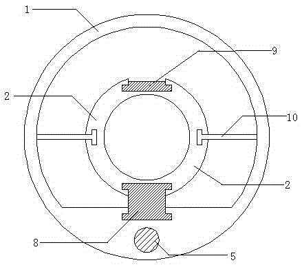
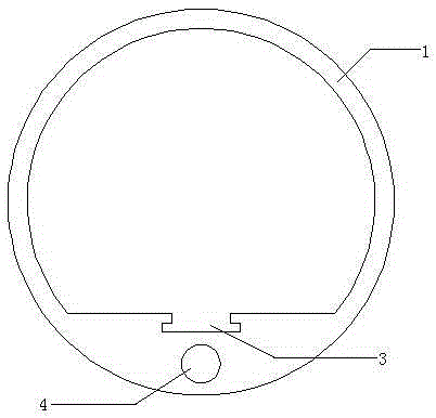
[0038] Such as figure 2 Horizontal section for kickoff picture ,include Such as image 3 The whipping outer cylinder 1 shown and Such as Figure 4 Kickoff pup 2 shown. The skew-making outer cylinder 1 is a hollow cylinder, one side of which is provided with a curved sliding groove 3 along the axial direction, and the skew-making outer cylinder 1 is provided with a columnar curved hole 4 near the edge of the curved sli...


PUM


Abstract

The invention discloses a segmented type deflecting screw drill for horizontal drilling. The segmented type deflecting screw drill comprises a deflecting part and a drilling part. The deflecting part comprises a deflecting outer cylinder and deflecting short joints. A bent slide groove is axially formed in one side in the deflecting outer cylinder. The deflecting short joints are each in a hollow column shape and are connected into the deflecting outer cylinder in an evenly-rotating mode. An inner slide groove and an outer slide groove are symmetrically and axially formed in the two sides of each deflecting short joint respectively. The upper end and the lower end of each outer slide groove are each connected with an outer slide plate in a rotating mode. An inner slide plate is installed in each inner slide groove in a matched mode. Every two adjacent deflecting short joints are connected. The drilling part comprises a drilling outer cylinder, a motor, a universal shaft, a transmission shaft and a drill bit. The top end of the drilling outer cylinder is connected with the deflecting short joint at the bottommost end through a bypass valve. The segmented type deflecting screw drill is simple in structure and low in manufacturing and use cost; high deflecting and drilling efficiency is still achieved in the narrow drilling environment or the environment with complex geological conditions; the segmented type deflecting screw drill is convenient to detach, assemble and transport, easy to use and durable in use.

Description

technical field [0001] The invention belongs to the technical field of drilling, and in particular relates to a segmented deflecting screw drilling tool for horizontal drilling. Background technique [0002] In horizontal drilling, deflection needs to be performed while drilling. The existing deflection pipeline is mainly composed of an elastic shell and a flexible drill pipe with an inner sleeve. The elastic shell needs to be transported and assembled before drilling and deflection can be performed; The elastic shell has an elastic bending structure, and the processing and manufacturing are relatively complicated; when the drilling environment is relatively narrow, the deflection efficiency of the existing deflection pipeline is relatively slow; and due to the complex geological environment, it is inevitable to encounter relatively hard rock formations , if the same power is maintained for continuous operation, it may cause damage to the drill bit or even the motor assembly...

Claims


Application Information

Patent Timeline
Patent Type & Authority Applications(China)
IPC IPC(8): E21B3/00E21B7/08
CPCE21B3/00E21B7/068
Inventor 徐永和刘华文王涛
Owner YANCHENG XINYONGJIA PETROLEUM MACHINERY MFG
Features
  • R&D
  • Intellectual Property
  • Life Sciences
  • Materials
  • Tech Scout
  • Unparalleled Data Quality
  • Higher Quality Content
  • 60% Fewer Hallucinations
Learn More