
Rotation separation tool for drilling

A technology of rotary separation and tools, which is applied in the direction of drilling driving devices, drilling equipment, earthwork drilling and production in the wellbore, and can solve the problems of increasing the number of drill string lifts, breaking, and damage to the drill string

Inactive Publication Date: 2016-03-02
SOUTHWEST PETROLEUM UNIV +2
View PDF5 Cites 0 Cited by
  • Summary
  • Abstract
  • Description
  • Claims
  • Application Information

AI Technical Summary

Problems solved by technology

During the drilling process, different formations exert different resistance on the drill bit, which makes the torque transmitted by the drill string exceed the normal drilling torque, which may cause damage or fracture of the drill string
As a result, the number of drill string lifts is increased, and the drilling operation time and operation cost are increased.

Method used


Image

  • Rotation separation tool for drilling
  • Rotation separation tool for drilling
  • Rotation separation tool for drilling

Examples


Embodiment Construction

[0028] Below in conjunction with accompanying drawing, the present invention is described in detail.

[0029] In order to make the object, technical solution and advantages of the present invention clearer, the present invention will be further described in detail below in conjunction with the accompanying drawings and embodiments. It should be understood that the specific embodiments described here are only used to explain the present invention, not to limit the present invention.

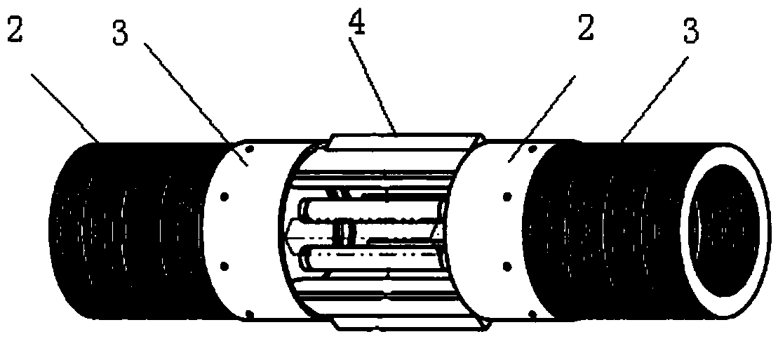
[0030] like Figure 1-8 Shown is an embodiment of a rotary separation tool for drilling in the present invention. A rotary separation tool for drilling includes: a power outer cylinder 1, a ratchet assembly 4, a bearing assembly 5 and an output shaft 7. The power outer cylinder 1. The inner wall is provided with a number of grooves 11 in the outer cylinder. The ratchet assembly 4 is composed of a number of ratchet plates. The ratchet plate is arc-shaped. The inner surface of the sheet is provide...


PUM


Abstract

The invention discloses a rotation separation tool for drilling, comprising an outer cylinder, a ratchet assembly, a spring seat, an output shaft, and the like. Through conical sliding fit between the ratchet assembly and the spring seat, conversion between radial displacement and axial displacement and conversion between torque and spring compression force are realized. When the rotation torque exceeds a set separation torque, separate rotation is implemented inside to prevent damage of excessive torque to a rock breaking tool connected with the output shaft. When the rotation torque does not exceed the set separation torque, a torque can be output continuously to complete work.

Description

technical field [0001] The invention relates to the field of drilling devices, in particular to a rotary separation tool for drilling. Background technique [0002] In the process of oil and gas field development, the rotary table and top drive are used to rotate the drill bit to break the rock from the ground, or use the screw motor to provide the drill bit to rotate and break the rock from the underground. Either way, the ultimate torque transfer to the drill bit (or other drill tool assembly) is through the drill pipe or drill collar. During the drilling process, different formations exert different resistance on the drill bit, which makes the torque transmitted by the drill string exceed the normal drilling torque, which may cause damage or fracture of the drill string. As a result, the number of liftings of the drill string is increased, and the drilling operation time and operation cost are increased. Contents of the invention [0003] The purpose of the present in...

Claims


Application Information

Patent Timeline
IPC IPC(8): E21B4/00
Inventor 王川金浩孔祥领谢真强黎俊周旭楚飞
Owner SOUTHWEST PETROLEUM UNIV
Learn More