
Water conservancy balance heat metering system and method

A technology of water balance and heat metering

Inactive Publication Date: 2016-03-02
高继升
View PDF8 Cites 12 Cited by
  • Summary
  • Abstract
  • Description
  • Claims
  • Application Information

AI Technical Summary

Problems solved by technology

2. Due to the difference in the location of the households, even if the area is the same, the heat consumption of the top-floor side users and the middle household type will be 2-3 times different when the temperature is the same.
3. Because of the quality problems of heat meters and water quality, according to statistics: after installing heat meters, only 30% of them can be used after one year, and only 10% of them can be used after three years
4. The heat meter is a measuring instrument, and it is required to be inspected once a year. Its maintenance workload is huge and the cost is high, and it is impossible to maintain it every year.
5. Water conservancy balance is the premise of heat metering working conditions. Metering can only be performed on the premise of heat supply balance. Without water conservancy balance, the user's on-demand distribution cannot be achieved.
Therefore, the distributor method is very difficult to promote in our country, and there is almost no promotion
[0011] (2) Behaviors such as replacing radiators, installing radiators, and blocking radiators by resident users without permission will affect the measurement effect
[0012] (3) The number of distribution meters is large, the workload of transcription is heavy, and it disturbs the people
[0013] (4) Not suitable for radiant floor heating systems
[0016] In actual engineering use, there are still many problems that are difficult to solve and overcome in the heat metering device of the on-off time area method, and the heat cost cannot be allocated fairly and reasonably.
These problems include: 1. In the general on-off time area heat metering system, electric ball valves are used to switch on and off, and the flow rate cannot be set. Generally, the flow rate of the bottom layer is 30-50% larger than that of the top layer.
2. Use the flow control circuit breaker. If the residents of the same area of ​​a building adopt the same flow rate, and the location of the residents is different, the top floor side users and the middle apartment type, when the temperature is the same, the opening time of the flow control circuit breaker is 2-3 times different. , If the charge is based on on-off time alone, the common people cannot accept it. 3. If the flow rate is gradually increased outward based on the flow rate per square meter of the intermediate apartment type, the proportional coefficient is not easy to determine. Even if it is determined, the common people will not accept it.
4. If the surrounding residents of a household do not move in, due to the thermal conductivity, the opening time of the flow control circuit breaker of this household will be prolonged, resulting in overcharging

Method used


Image

  • Water conservancy balance heat metering system and method

Examples


Embodiment 1

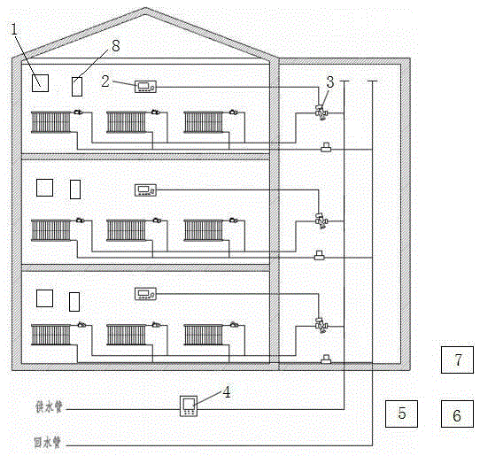
[0045] like figure 1 As shown, the present invention discloses a water conservancy balance heat metering system, comprising an indoor wireless temperature sensor 1, an indoor temperature controller 2, a flow on-off controller 3, a building heat meter 4, a data collector 5, a base station 6 and a data management Center 7. The building heat meter 4 is located at the total heating entrance of each building and is used to measure the total heat of the building. The flow on-off controller 3 is installed on the branch pipeline at the entrance of each household to control the heating pipeline of the household. The on / off of the flow control (the flow control circuit breaker is generally installed on the heating pipe of each household, and it can be installed on the return water pipe in special cases, there is no special requirement).

[0046] The indoor temperature controller 2 is located in each household and is used to set and control the indoor temperature. The indoor temperature...

Embodiment 2

[0051] A water conservancy balance heat metering method, comprising the steps of:

[0052] 1) Construct the water balance heat metering system, the specific construction process is as follows:

[0053] Install the building heat meter 4 at the total heating entrance of each building to measure the total heat of the building; install the flow on-off controller 3 on the branch pipeline at the entrance of each household to control the opening and closing of the household heating pipeline / off; install indoor temperature controller 2 and indoor wireless temperature sensor 1 in the room of each household, the indoor temperature controller is used to set and control the indoor temperature, and the sensor is used to collect the actual temperature in the room; the indoor temperature controller is passed through Wired or wireless connection with the control end of the flow on-off controller, used to control the on / off of the flow on-off controller through the indoor temperature controll...


PUM


Abstract

The invention discloses a water conservancy balance heat metering system and method, and relates to the technical field of devices or methods for measuring heat. The system comprises indoor wireless temperature sensors, indoor temperature controllers, flow switch-on and switch-off controllers, building heat meters and data acquirers, wherein each building heat meter is positioned at a total heating inlet of the corresponding building; each flow switch-on / switch-off controller is mounted on a branch pipe of an entrance of the corresponding house; each indoor temperature controller is positioned in the corresponding house and is connected with a control end of the corresponding flow switch-on and switch-off controller in a wired or wireless mode; each sensor is arranged in the corresponding house; each data acquirer is arranged in the corresponding building; and the data acquirers are used for acquiring relevant information of the sensors, the indoor temperature controllers, the flow switch-on and switch-off controllers and the building heat meters. According to the method, water conservancy working condition balance is implemented by an adjusting means, users can accept the relatively reasonable apportion mode, heating cost is reduced, energy conservation and emission reduction are promoted, and comfort level of residents is improved.

Description

technical field [0001] The invention relates to the technical field of devices or methods for measuring heat, in particular to a water conservancy balance heat metering system and a metering method. Background technique [0002] The realization of metered heat supply is an inevitable trend in the development of the heating industry, and it is also the inevitable result of the marketization of heat supply, and an important symbol of "heat commodity". Our government also attaches great importance to this, and has included this work as an important part of "energy saving and emission reduction". Since 2007, the state has formulated three laws and regulations on "energy saving and emission reduction". It is imperative to pay attention to "energy saving and emission reduction" and the development of heat supply metering, especially the promotion of heat supply metering. Moreover, the government started from the architectural design of the construction source, requiring new resi...

Claims


Application Information

Patent Timeline
IPC IPC(8): F24D19/10G01K17/06
CPCF24D19/1048G01K17/06G01K2217/00
Inventor 高继升高继成高继中苑林林隋金恒
Owner 高继升
Learn More