Electroplating drying machine

A dryer and rack technology, applied in the direction of dryers, drying, progressive dryers, etc., can solve problems such as complex operation, achieve good cooling effect, reduce manual operation, and extend the path

Inactive Publication Date: 2016-03-02
CHONGQING PENGLEI AUTO PARTS CO LTD
View PDF0 Cites 1 Cited by
  • Summary
  • Abstract
  • Description
  • Claims
  • Application Information

AI Technical Summary

Problems solved by technology

Then put the auto parts into the dryer for drying. After drying, the auto parts will be passed out along the chain transmission. Next, the auto parts will be put into the tray by manual wearing gloves for cooling. Drying and cooling process separated, the operation is more complicated

Method used


Image

  • Electroplating drying machine

Examples


Embodiment 1

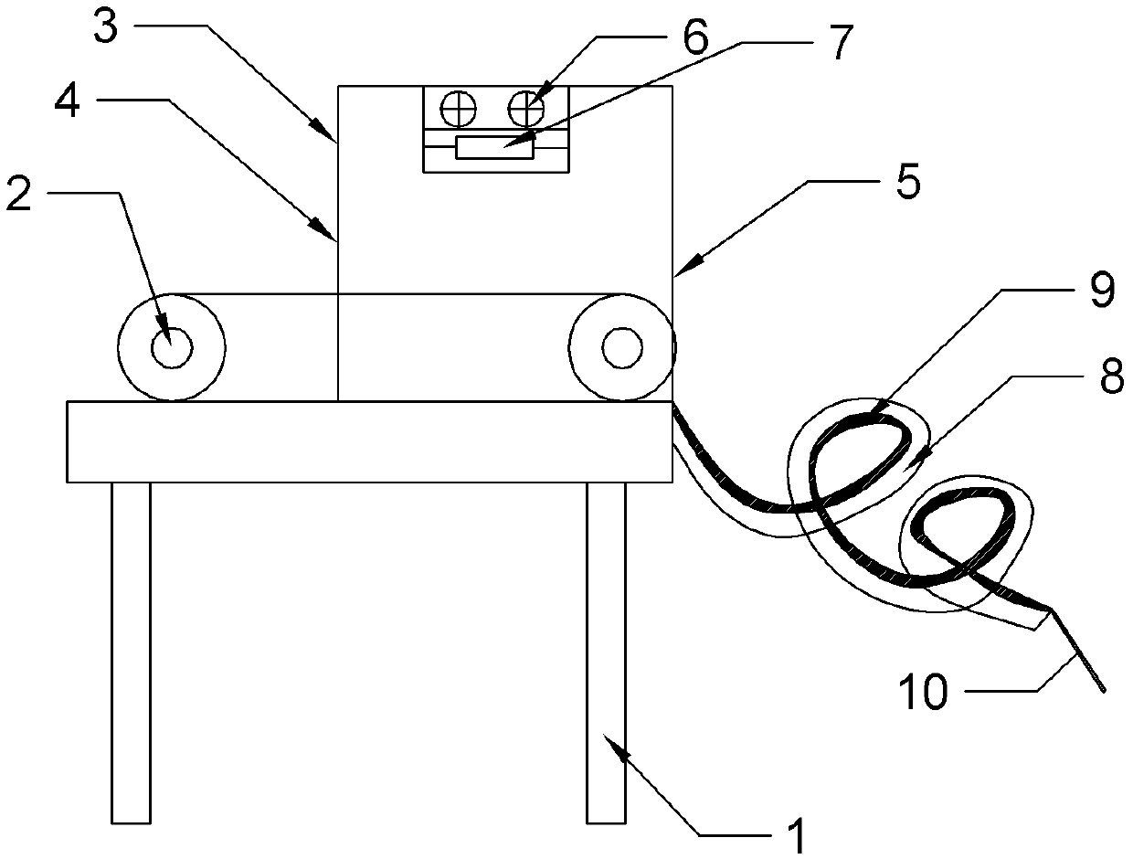
[0015] Example 1, such as figure 1 As shown, the electroplating dryer includes a frame 1 and a transmission mechanism 2, the transmission mechanism 2 is fixed on the frame 1, and the transmission mechanism 2 is a chain drive, which facilitates the contact of air with auto parts and increases the drying effect. A sealing cover 3 is arranged above the conveying mechanism 2 , and an inlet 4 and an outlet 5 are respectively arranged on both sides of the sealing cover 3 , and the conveying mechanism 2 passes through the sealing cover 3 and is flush with the outlet 5 . A fan 6 and an electric heating tube 7 are sequentially arranged in the sealing cover 3 from top to bottom, and the electric heating tube 7 is located directly above the transmission mechanism 2 to facilitate drying of auto parts by hot air. The outlet end of the conveying mechanism 2 is provided with a spiral pipe 8, and the pipe 8 is inclined downward, and the angle between the pipe 8 and the horizontal plane is 30°...

Embodiment 2

[0016] Embodiment 2 is different from Embodiment 1 in that the angle between the pipeline 8 and the horizontal plane is 40°, and the temperature of the cold water layer 9 is 10°.

Embodiment 3

[0017] Embodiment 3 differs from Embodiment 1 in that the angle between the pipeline 8 and the horizontal plane is 50°, and the temperature of the cold water layer 9 is 20°.

[0018] Firstly, the cleaned auto parts are placed on the transmission mechanism 2, and the auto parts are brought into the sealing cover 3 along with the transmission of the transmission mechanism 2, and the electric heating tube 7 generates heat after being energized, and the fan 6 transfers the heat of the electric heating tube 7 along the Blow in a downward direction to the surface of auto parts, which is convenient for drying auto parts. After drying, the auto parts enter the pipe 8 along with the transmission mechanism 2. Under the gravity of the auto parts, the auto parts move downward along the spiral pipe 8. The cold water layer 9 in the pipe 8 can absorb the heat on the auto parts. Let it cool down and cool down. The cooled car parts thus go directly into the tray for collection.


PUM


Abstract

The invention relates to the field of electroplating of automobile parts, in particular to an electroplating drying machine. The electroplating drying machine comprises a machine frame and a conveying mechanism; the conveying mechanism is fixed on the machine frame; a sealing cover is disposed on the upper portion of the conveying mechanism; an inlet and an outlet are formed at the two sides of the sealing cover respectively; a fan and an electrical heating tube are disposed in the sealing cover in sequence from top to bottom; a spiral pipeline is disposed at the outlet end of the conveying mechanism; the pipeline is inclined downwards, and a cold water layer is disposed in the pipeline. Drying and cooling are combined, the labor cost is reduced, and the work efficiency is improved.

Description

technical field [0001] The invention relates to the field of electroplating processing of auto parts, in particular to an electroplating dryer. Background technique [0002] Electroplating is the process of plating a thin layer of other metals or alloys on the surface of certain metals using the principle of electrolysis. It is a process of using electrolysis to attach a layer of metal film to the surface of metal or other material parts to prevent metal oxidation. Improve wear resistance, electrical conductivity, reflective properties, corrosion resistance and improve appearance. Electroplating is divided into rack plating, barrel plating, continuous plating and brush plating, which are mainly related to the size and batch size of the parts to be plated. Among them, barrel plating is suitable for small parts, such as fasteners, washers, pins, etc., among which auto parts are all finished by barrel plating. During the barrel plating process, the electroplating cylinder rol...

Claims


Application Information

Patent Timeline
Patent Type & Authority Applications(China)
IPC IPC(8): F26B15/12F26B25/00C25D21/00
Inventor 何令
Owner CHONGQING PENGLEI AUTO PARTS CO LTD
Why Eureka
Try Eureka