Large-scale paraboloid antenna surface operation angle control and loading measurement system

A parabolic antenna, working angle technology, applied in the direction of antenna, antenna parts, antenna support/installation device, etc., can solve the problems such as impossible to ensure the horizontal state of the theodolite, complex structure of large-diameter parabolic antenna, affecting the measurement accuracy of the reflector, etc. , to achieve the effect of simple structure, reliable and effective fixation, and error avoidance

Inactive Publication Date: 2016-03-02
CHENGDU JINJIANG ELECTRONICS SYST ENG
View PDF4 Cites 6 Cited by
  • Summary
  • Abstract
  • Description
  • Claims
  • Application Information

AI Technical Summary

Problems solved by technology

However, there are two insurmountable obstacles in this measurement method, which affect the measurement accuracy of the reflective surface:
[0003] 1. The theodolite is installed on a large reflective surface. Due to the influence of wind load, the antenna shakes. It is impossible to ensure that the theodolite is in a horizontal state at any time, and the sufficient and necessary condition for the theodolite to work in a free state is horizontal
[0004] 2. Due to the complexity of the self-weight deformation of large antennas, and the mathematical model is difficult to determine during mechanical analysis
However, the structure of the large-aperture parabolic antenna is complex, and it is difficult to establish an accurate mathematical model due to the influence of the antenna's own weight deformation, wind load and other factors, so it is very difficult to give an accurate preset value

Method used


Image

  • Large-scale paraboloid antenna surface operation angle control and loading measurement system
  • Large-scale paraboloid antenna surface operation angle control and loading measurement system
  • Large-scale paraboloid antenna surface operation angle control and loading measurement system

Examples


Embodiment Construction

[0033] The present invention will be further described below in conjunction with accompanying drawing, protection scope of the present invention is not limited to the following:

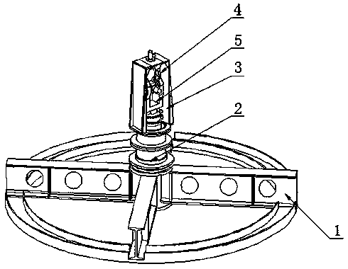
[0034] Such as figure 1 As shown, a large-scale parabolic antenna profile working angle control and loading measurement system includes a high-strength bracket 1, a rotating head 2, an afterburner cover 3, a handle combination 4 and a theodolite 5, and the rotating head 2 is installed on a high-strength On the bracket 1, the booster cover 3 is installed on the swivel head 2 through threaded connection, theodolite 5 is installed on the swivel head 2 through threaded connection, the theodolite 5 is located in the booster cover 3, and the handle combination 4 is installed on the booster cover through threaded connection 3, handle combination 4 is connected with theodolite 5;

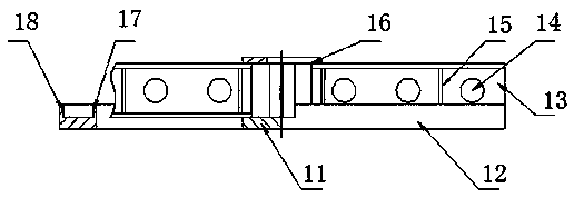
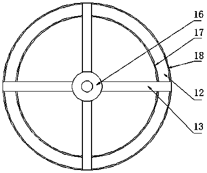
[0035] Such as figure 2 , 3 As shown, wherein the high-strength support 1 includes a positioning plate 12, several support f...


PUM

PropertyMeasurementUnit
Angleaaaaaaaaaa

Abstract

The present invention discloses a large-scale paraboloid antenna surface operation angle control and loading measurement system. The large-scale paraboloid antenna surface operation angle control and loading measurement system comprises a high-strength support (1), a rotating head (2), a reinforcing cover (3), a handle combination (4) and a theodolite (5). The rotating head (2) is installed on the high-strength support (1) through threaded connection; the reinforcing cover (3) is installed on the rotating head (2) through threaded connection; the theodolite (5) is installed on the rotating head (2) through threaded connection; the theodolite (5) is located in the reinforcing cover (3); the handle combination (4) is installed on the reinforcing cover (3) through threaded connection; and the handle combination (4) is connected with the theodolite (5). The large-scale paraboloid antenna surface operation angle control and loading measurement system is able to measure and control the operation angle of the large-scale paraboloid antenna surface, eliminate measurement errors caused by factors such as wind loading, dead weight, positioning error and the like, and ensure the measurement precision. Moreover the large-scale paraboloid antenna surface operation angle control and loading measurement system is able to effectively fix a theodolite and allow the theodolite to perform inclination measurement which cannot be realized in the prior art.

Description

technical field [0001] The invention relates to the control and measurement of the working angle of a large parabolic antenna profile, in particular to a large parabolic antenna profile working angle control and loading measurement system. Background technique [0002] The common methods for controlling and measuring the working angle of large parabolic antennas include center positioning method and non-center positioning method. Among them, the center positioning method is divided into arc angle method and chord angle method, because the chord angle method requires the accuracy of the chord, and the chord Relatively large antennas are longer and more difficult to control than arcs. Usually, domestic antennas with a caliber of less than 10m use a rotating sample to test the accuracy of the main reflector of the antenna. Antennas above 10m are generally measured with optical instruments at the antenna’s upward position (α=90°). However, there are two insurmountable obstacle...

Claims


Application Information

Patent Timeline
IPC IPC(8): H01Q1/12H01Q3/02H01Q15/16
CPCH01Q1/1264H01Q3/02H01Q15/16
Inventor 蔡云林鹏霍建忠李亚红毛梓铸杨雪峰
Owner CHENGDU JINJIANG ELECTRONICS SYST ENG
Why Eureka
Try Eureka