Distributed interference coordination method based on beam shape matching in 3D-MIMO system

A 3D-MIMO, 1.3D-MIMO technology, applied in the field of interference coordination scheme, can solve the problems of interference suppression between users, inability to adjust the beam half-power beam width, and poor service quality for edge users.

Active Publication Date: 2016-03-02
CERTUS NETWORK TECHNANJING
View PDF6 Cites 24 Cited by
  • Summary
  • Abstract
  • Description
  • Claims
  • Application Information

AI Technical Summary

Problems solved by technology

However, it can neither adjust the half-power beam width of the beam, nor suppress the interference between users, and the service quality of the edge users is poor.

Method used


Image

  • Distributed interference coordination method based on beam shape matching in 3D-MIMO system
  • Distributed interference coordination method based on beam shape matching in 3D-MIMO system
  • Distributed interference coordination method based on beam shape matching in 3D-MIMO system

Examples


Embodiment 1

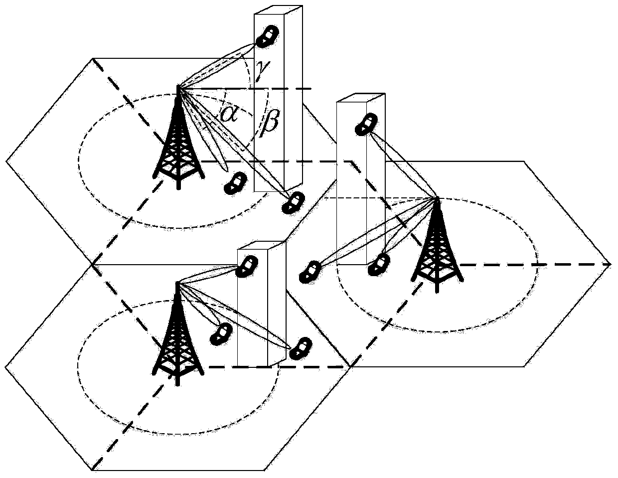
[0101]Considering the 3D channel scenario of seven cells in a cell cluster, the base station antenna array of each horizontal sector has 12 horizontal antennas and 16 vertical antennas. The precoding algorithm adopts MRT precoding. For other simulation parameters, refer to Table 1.

[0102] Table 1 User 3D distribution scene simulation parameters

[0103]

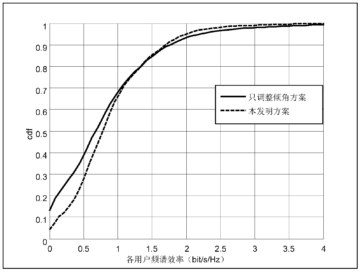
[0104] Depend on image 3 It can be seen that the proposed scheme can improve the performance of edge users compared with the scheme that only adjusts the inclination angle. This is because the proposed scheme can adjust the beam width and expand the beam coverage, which can effectively improve the service quality of edge users. The user maximum rate of the scheme of the present invention is lower than only adjusting the inclination scheme, and this is by Figure 5 It can be seen that the beam main direction gain of the scheme of the present invention is slightly smaller than that of the scheme of only adjusting the in...

Embodiment 2

[0107] The base station antenna array of each horizontal sector has 12 horizontal antennas and 32 vertical antennas, and the other scene configurations are the same as those in Embodiment 1.

[0108] Such as Figure 6 As shown, as the number of antennas in columns increases, the beams formed by the antennas become narrower, which can serve target users more accurately. Therefore, the maximum spectral efficiency of users increases by about 3 bit / s / Hz compared with the scenario of 16 antennas in columns. In addition, compared with the scenario with 16 antennas in columns, the performance of edge users in the solution of the present invention is slightly improved, because the number of column antennas increases and the beam becomes narrower, and the adjustment of the half-power beam width in this solution improves the overall performance of the service user group It is more effective. Compared with the scheme of only adjusting the tilt angle with a fixed half-power beam width, th...

Embodiment 3

[0110] The precoding algorithm adopts SLNR precoding, and other scene configurations are the same as those in Embodiment 1.

[0111] Such as Figure 8 and Figure 9 As shown, after changing MRT precoding to SLNR precoding, the cdf curve of user spectral efficiency does not change significantly, but the spectral efficiency of a certain level sector of each scheme under each SNR situation is slightly lower than that of MRT precoding.

[0112] System overhead and computational complexity analysis:

[0113] Only the tilt adjustment scheme only needs to know the user's position information, the feedback overhead is small, and the computational complexity of each beam The scheme of the present invention only needs to know the location information of the user, the feedback overhead is very small, and it is a distributed optimization scheme, the optimization process is simple to operate, and the computational complexity of each search is relatively low as O(B 2 N), B is the size o...


PUM


Abstract

The invention discloses a distributed interference coordination method based on beam shape matching in a 3D-MIMO system. The method comprises steps of: initializing the beam direction of each vertical sector of a base station in each horizontal sector; determining an initial service beam to which each user belongs according to the 3D position of the user, and updating the direction and a half-power beam width of the initial service beam according to the elevation angle information of the user in each vertical beam; and substituting the updated direction and the updated half-power beam width into an established optimization problem and searching an optimal antenna weight so as to achieve lowest interference of the beams in different vertical sectors, increase a signal-to-interference-noise ratio, and guarantee system performance. For a scheme in which only an inclination angle is adjusted, the method has a biggest advantage that the direction and the half-power beam width of the antenna beam are simultaneously adjusted. Thus, not only is the antenna gain in a target direction achieved, but also interference in other directions is inhibited such that the beams accurately serve the user. By adjusting the half-power beam width, the method expands coverage and effectively improves the service quality of edge users.

Description

technical field [0001] The invention relates to an interference coordination scheme in a 3D-MIMO system under 3D distribution of users in wireless communication, in particular to a distributed interference coordination method based on beam shape matching in the 3D-MIMO system. Background technique [0002] Limited by the traditional base station antenna architecture, the existing MIMO transmission schemes generally can only control the spatial distribution characteristics of signals in the horizontal plane, and have not fully utilized the degree of freedom in the vertical dimension of the 3D channel, let alone deeply excavated MIMO technology. Potential for improving the overall efficiency and performance of mobile communication systems and end-user experience. In recent years, the Massive MIMO (Very Large MIMO or Massive MIMO) system, which is equipped with a large number of antennas at the base station and can communicate with multiple co-channel users at the same time, ha...

Claims


Application Information

Patent Timeline
Patent Type & Authority Applications(China)
IPC IPC(8): H04B7/04H04B7/06H04B7/08
CPCH04B7/0413H04B7/0491H04B7/0695H04B7/088Y02D30/70
Inventor 张国梅任俊臣李杰吕刚明李国兵
Owner CERTUS NETWORK TECHNANJING
Why Eureka
Try Eureka