Arch column method for building large-scale underground structure in shallow buried rock stratums

An underground structure and arch-column method, applied in underground chambers, mining equipment, earth-moving drilling, etc., can solve the problems of difficult deformation control, many excavation divisions, and large construction risks, so as to reduce construction risks and reduce construction risks. Small excavation span, the effect of avoiding the fall of the top arch

Active Publication Date: 2016-03-09
BEIJING URBAN CONSTR DESIGN & DEV GRP CO
View PDF5 Cites 4 Cited by
  • Summary
  • Abstract
  • Description
  • Claims
  • Application Information

AI Technical Summary

Problems solved by technology

[0003] The purpose of the present invention is to propose a construction method for building multi-layer and multi-span underground structures in shallow buried rock formations, which solves the problems of many excavation divisions, low construction efficiency, high construction risk, and difficulty in deformation control existing in the traditional underground excavation construction method and other problems, forming a method of convenient construction, high efficiency, low construction risk, good control of formation deformation, and low cost when building large-scale underground structures in shallow buried rock formations

Method used


Image

  • Arch column method for building large-scale underground structure in shallow buried rock stratums
  • Arch column method for building large-scale underground structure in shallow buried rock stratums
  • Arch column method for building large-scale underground structure in shallow buried rock stratums

Examples


Embodiment Construction

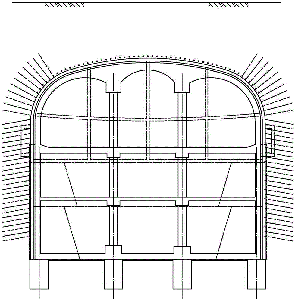
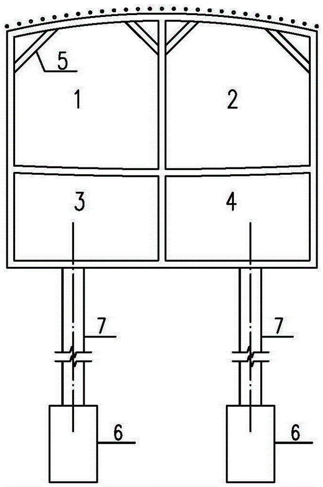
[0053] see Figure 1-Figure 7 Shown: implementation example 1, the construction steps are as follows:

[0054]1. Enter the basement floor from the upper guide hole of the construction cross passage, excavate the upper guide hole 1 and 2 (the distance between the left and right guide holes is staggered), set up advance support (when necessary) and anchor rods, and implement initial support , The top steel diagonal brace, after entering the pilot tunnel from the construction cross passage, excavate the lower pilot tunnel 3 and pilot tunnel 4 (the pilot tunnels are staggered), manually dig holes under the center column with water drill, pour the pile foundation, and place it above the pile foundation Steel pipe columns are installed in sections, the interior of the column is filled with micro-expansion concrete, and the exterior of the column is backfilled with fine sand, supplemented by grouting measures if necessary;

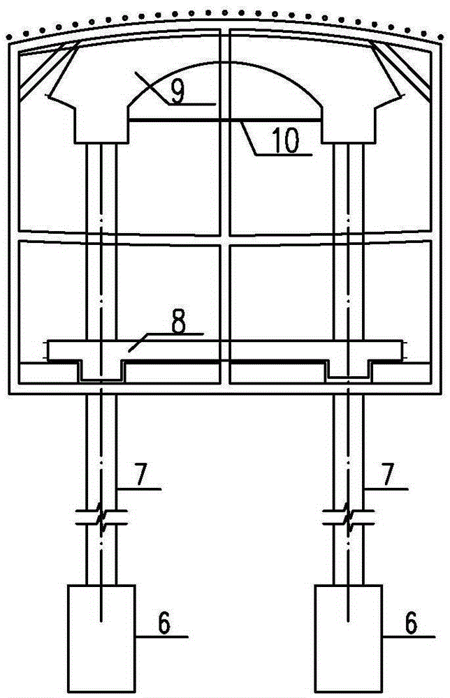
[0055] 2. Lay the floor formwork in the middle cave, pour ...


PUM


Abstract

The invention relates to an arch column method for building a large-scale underground structure in shallow buried rock stratums. The method comprises the following steps of: 1, separately excavating underground one-storey middle pilot tunnels, constructing primary supports, and constructing pile foundations and steel pipe columns at the positions of middle columns; 2, constructing secondary linings including underground one-storey floors, steel pipe columns, roof timbers, roof arches and the like, and waterproof layers in middle tunnels; 3, symmetrically excavating underground one-storey two-side pilot tunnels, constructing primary supports, and constructing pile foundations and side columns under side walls; 4, constructing secondary linings including floors, vertical walls, edge arches and the like in side tunnels and waterproof layers, and disassembling temporary supports; 5, under the protection of underground one-storey structures, downwards excavating an underground second-storey structure with large-scale machinery, besides, constructing side wall bolt spray supports or slab rib type anchored bolt retaining wall supports, and pouring underground second-storey floors, side walls and waterproof layers; and 6, sequentially downwards excavating a plurality of underground storeys, besides, constructing side wall supports, and pouring floors, side walls and waterproof layers of corresponding storeys. The method disclosed by the invention is convenient to construct, high in efficiency, small in construction risks, good in stratum deformation control, and low in building cost.

Description

technical field [0001] The invention relates to the technical field of underground construction engineering or tunnel engineering, in particular to the underground excavation construction technology for building multi-layer and multi-span underground structures in shallow buried rock formations, and is a construction method for building large-scale underground structures in shallow buried rock formations. Background technique [0002] At present, with the development of cities and the construction of rail transit, more and more multi-layer, multi-span and large-scale underground structures are built in shallow buried rock formations. In order to avoid the impact on ground transportation, buildings (structures) and pipelines, Usually have to adopt underground excavation method construction. Traditional underground excavation methods include pillar hole method, double side wall pilot pit method, arch cover method, hole pile method and so on. The column hole method first excav...

Claims


Application Information

Patent Timeline
Patent Type & Authority Applications(China)
IPC IPC(8): E21D13/02
CPCE21D13/00
Inventor 程小虎杨艳青鲁卫东杨秀仁周婷婷易立朱剑焦健赵明张建波扈世民刘彪段秀春
Owner BEIJING URBAN CONSTR DESIGN & DEV GRP CO
Why Eureka
Try Eureka