
Method of measuring influence of radome on antenna array direction-finding performance

A technology of antenna array and radome, which is applied to direction finders for measuring directions, direction finders using radio waves, monitoring/testing of radio wave directional devices, etc. Test complex workload and other issues to achieve the effect of reducing complexity and workload, small workload, and simple process

Inactive Publication Date: 2016-03-09
NANJING UNIV OF AERONAUTICS & ASTRONAUTICS
View PDF2 Cites 9 Cited by
  • Summary
  • Abstract
  • Description
  • Claims
  • Application Information

AI Technical Summary

Problems solved by technology

However, this method needs to determine the specific working mode and radiation characteristics of the antenna array, which increases the complexity of the test and the workload of the calculation, and cannot meet the requirements for the special antenna-radome system

Method used


Image

  • Method of measuring influence of radome on antenna array direction-finding performance
  • Method of measuring influence of radome on antenna array direction-finding performance
  • Method of measuring influence of radome on antenna array direction-finding performance

Examples


Embodiment 1

[0097] Embodiment 1: In this embodiment, a certain antenna array-radome system is taken as an example to describe the method in detail, and the position of the antenna array is shown in Table 2. In this embodiment, the working frequency band of the system is 2-18 GHz, and the five-element antenna array is inside the radome to form an interferometer direction finding system, and the direction finding is realized by using the principle of long and short baselines. The schematic diagram of the antenna array in this example is as follows Figure 7 As shown, if the center of the radome is taken as the origin of the coordinates, the coordinates of each antenna are defined according to Table 2, and the antenna unit selects a uniform surface. In the present embodiment, the radome uses a tangent oval shape, its length L=1000mm, and its diameter is D 0 =800mm, the schematic diagram is as follows Figure 8As shown, the radome model is established using the modeling software CATIA, as s...

Embodiment 2

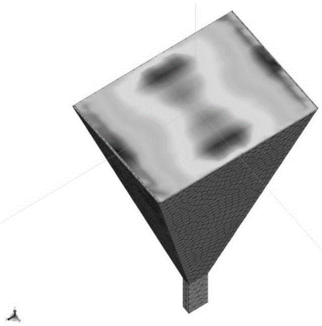
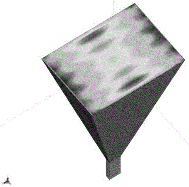
[0101] Embodiment 2: In this embodiment, the method is described in detail by taking a quadruple antenna array-radome system operating in the frequency band of 0.8-6 GHz as an example. Inside the radome is a four-element antenna array, which constitutes an interferometer direction finding system. The schematic diagram of the antenna array in this example is as follows Figure 10 As shown, the lengths of the respective baselines are L1=188mm, L2=144mm, and L3=239mm, and the antenna unit selects a uniform mouth surface. The radome uses a square plate structure radome with a side length of 1000mm. The relative permittivity and thickness of each layer of the radome wall are shown in Table 1.


PUM


Abstract

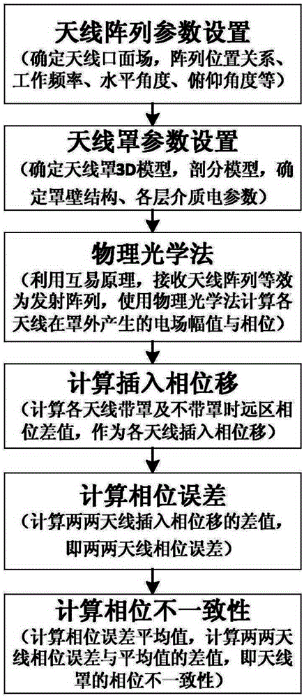
The invention discloses a method of measuring the influence of a radome on the antenna array direction-finding performance. The method comprises the steps of determining various parameters in an antenna array, including antenna coordinates, antenna equivalent aperture data and radome geometry and the like; calculating the amplitude and phase of an electric field generated by each antenna at a far region outside the radome by using a physical optics method; calculating the insertion phase delay of an arbitrary antenna unit in the antenna array; calculating the phase error, that is the difference of the insertion phase delay between two antennas; and calculating an average value of the phase errors of any two antennas in the antenna array system, and finally calculating the difference between the phase error of the two antennas and the average value, that is the phase inconsistency of the radome, for measuring the influence of the radome on the antenna array electrical performance. Compared with the prior art, the invention has the advantages of requiring no knowledge of the working pattern or radiation characteristics of the antenna array in the radome, reducing the complexity and amount of calculation, facilitating requirements of special systems and so forth.

Description

technical field [0001] The invention relates to a method for measuring the influence of a radome on the direction-finding performance of an antenna array, and belongs to the technical field of radar antennas. Background technique [0002] The antenna array arranged in the radome can be used to realize functions such as direction finding, positioning and tracking. For example, the reconnaissance system installed on the aircraft can carry out reconnaissance in a wide range of space without being restricted by terrain conditions. It is widely used in civilian fields. In order to meet the requirements of aircraft aerodynamic performance and protect the antenna system from harsh environments such as high temperature and static electricity, the exterior of the antenna system should be protected by a radome. In the antenna system, reducing the influence of the radome on its internal antenna array is of great significance to ensure the normal operation of the antenna system. [0...

Claims


Application Information

Patent Timeline
Patent Type & Authority Applications(China)
IPC IPC(8): G01S3/02G01S3/48
CPCG01S3/023G01S3/48
Inventor 曹群生眭韵王毅李高生明永晋李豪
Owner NANJING UNIV OF AERONAUTICS & ASTRONAUTICS
Learn More