
Real-time self-adaptive contour error estimation method

A contour error and self-adaptive technology, applied in the direction of instruments, digital control, control/regulation systems, etc., can solve the problem of estimation accuracy and small calculation amount, and achieve the effect of good estimation error effect, accurate estimation accuracy and high robustness

Inactive Publication Date: 2016-03-09
SHANGHAI JIAO TONG UNIV
View PDF7 Cites 16 Cited by
  • Summary
  • Abstract
  • Description
  • Claims
  • Application Information

AI Technical Summary

Problems solved by technology

However, as mentioned above, these methods have various deficiencies, especially when high-speed motion and ideal trajectory curvature are large, all methods cannot maintain good estimation accuracy while ensuring a small amount of calculation to meet real-time calculation requirements. requirements

Method used


Image

  • Real-time self-adaptive contour error estimation method
  • Real-time self-adaptive contour error estimation method
  • Real-time self-adaptive contour error estimation method

Examples


Embodiment 1

[0062] This example is to illustrate the excellent performance of the method proposed by the present invention when the curvature of the curve becomes larger. Here with the parabola y=0.5x 2 ,x∈(-5,5) is used as an ideal curve for trajectory tracking, as shown in Figure 4(a). Because for this parabola, the curvature of its curve gradually increases with x from infinity to 0, as shown in Figure 4(b).

[0063] When the moving speed is 50mm / s, the estimation errors of the three methods are shown in Fig. 5(a), because the estimation errors of the second type method and the method of the present invention are obviously smaller than the first type, so they are almost parallel to the abscissa. In order to display the results more clearly, only the estimation errors of the second type and the method of the present invention are presented in Fig. 5(b), and the scale of y is enlarged. At the same time, the results are summarized in Table 1 below:

[0064] Table 1 Comparison of the es...

Embodiment 2

[0068] This example is to illustrate the good performance of the method proposed by the present invention at high speed. Here, a circle with a radius of 30 mm is used as an ideal curve for trajectory tracking. The results are summarized in Table 2 below

[0069] Table 2 Comparison of estimation errors of the three estimation methods as the motion speed increases

[0070]

[0071] It can be seen from Table 2 that the present invention has a more accurate estimation accuracy than the traditional method no matter at a lower speed or a higher speed. And with the increase of speed, no matter the estimation error of the first type or the second type method all increases sharply, while the method proposed by the present invention also increases, but the increase is very slow. Therefore, compared with traditional methods, the proposed method not only has higher estimation accuracy, but also has higher robustness.


PUM


Abstract

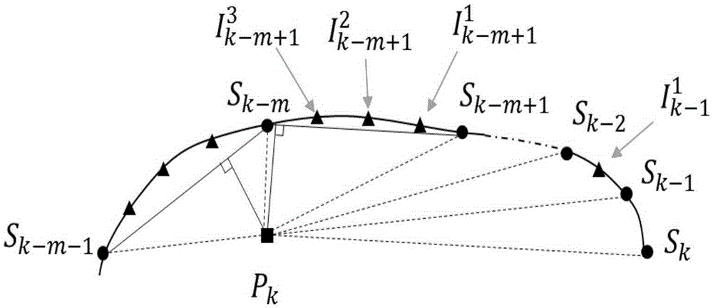
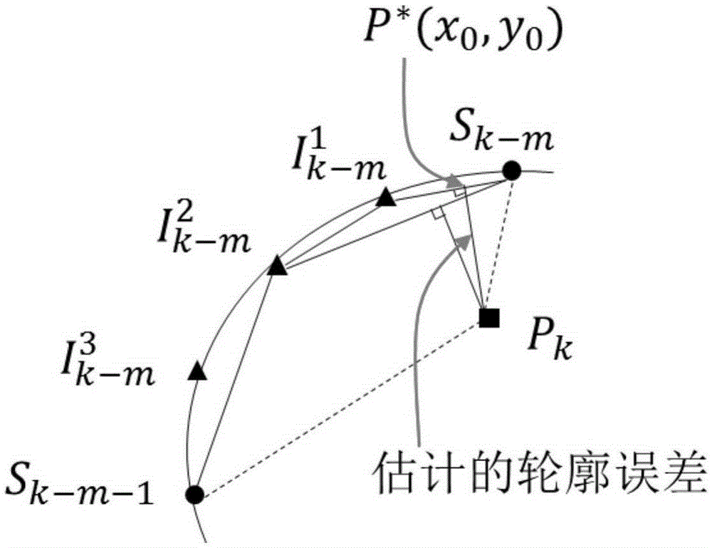
The invention discloses a real-time self-adaptive contour error estimation method, which can be used for a numerical control system or a contour controller of a robot. The contour error estimation method comprises the steps: generating extra interpolation points by properly modifying a conventional parameter curve interpolation method, wherein the generated extra interpolation points are only used for contour error estimation and do not serve as reference instructions of a motion controller; searching among original interpolation points the nearest point from an actual cutter position, preliminarily determining a search scope; and further determining foot points through a binary search method. A distance between the foot points and an actual cutter point is an estimated contour error. Compared with conventional estimation methods, the real-time self-adaptive contour error estimation method is more accurate in estimation precision. In particular, the method can still have a great effect and exhibit excellent algorithm robustness when the estimation effects of the conventional methods suddenly become bad in a condition with high speed movement and high curvature of a curve. Moreover, the method needs moderate computational complexity, fully meets the requirement of real-time applications, and is highly practical.

Description

technical field [0001] The invention relates to the field of numerical control systems, in particular to an online real-time error estimation method for contour control. Background technique [0002] In robots and CNC machine tools, a key goal is to make the robot or tool move along the ideal trajectory, and make the contour error between the actual trajectory and the ideal trajectory as small as possible. Due to non-linear factors such as friction, noise in the measurement signal, and mismatching of the dynamic characteristics of each axis, the contour error is inevitable. If only the movement of each axis is controlled independently, the contour error cannot be achieved as small as possible. Purpose. Therefore, considering multi-axis coupling factors, it is the mainstream practice of modern CNC system to comprehensively design the contour controller. In various contour controllers, the key step is to estimate the contour error in real time. [0003] At present, the cont...

Claims


Application Information

Patent Timeline
Patent Type & Authority Applications(China)
IPC IPC(8): G05B19/19
CPCG05B19/19G05B2219/35408
Inventor 奚学程蔡一天赵万生
Owner SHANGHAI JIAO TONG UNIV
Learn More