Solar module rear side encapsulation element and solar module

A solar module and backside encapsulation technology, applied in the field of solar modules, can solve problems such as low mechanical stability, inability to protect solar modules for a long time, and limited UV radiation resistance

Inactive Publication Date: 2016-03-09
HANWHA Q CELLS
View PDF8 Cites 2 Cited by
  • Summary
  • Abstract
  • Description
  • Claims
  • Application Information

AI Technical Summary

Problems solved by technology

Although it has improved hydrolysis resistance and good electrical insulation properties, it does not weatherproof long enough to protect solar modules in areas with many dust storms, sand storms and enhanced UV exposure
Therefore, this solar module has limited applicability for use in desert areas
[0005] Especially in desert areas, where solar modules are exposed to increased mechanical stress and enhanced UV exposure caused by sandstorms, the wear and tear of existing solar modules is higher
This is due to the fact that the polymer foils used have limited resistance to UV radiation and their mechanical stability against abrasion is too low in view of the required service life of up to twenty years

Method used


Image

  • Solar module rear side encapsulation element and solar module

Examples


Embodiment Construction

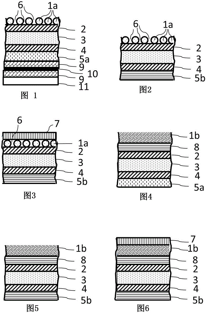
[0037] figure 1 A schematic and not to scale partial cross-sectional view of a solar module with a solar module backside encapsulation member according to a first embodiment is shown. The solar module has a front encapsulation member 11 and an encapsulation material 9 arranged on the back of the member, and the front of the front encapsulation member is the light incident surface of the solar module. In addition, the solar module includes solar cell strings 10 arranged on the back side of the front packaging member 11, the solar cell strings 10 are connected to each other and embedded in the packaging material 9, so that the solar cell strings 10 face the front packaging Both the side of the component 11 and the side of the solar cell string 10 facing away from the front-side encapsulation component 11 are surrounded by the encapsulation material 9 . In addition, the solar module has a solar module backside encapsulation component, which is arranged on the side of the solar c...


PUM

PropertyMeasurementUnit
diameteraaaaaaaaaa

Abstract

A solar module rear side encapsulation element having a laminate-type layer construction having at least one polymer plate or polymer foil (2,3,4,5a,5b,8) having a laminate surface is provided. The laminate-type layer construction has at least one protective layer having layer openings (6). The protective layer (1a, 1b) covers at least 70% of the laminate surface by a covering area, and due to the layer openings (6) at least 15% and maximum 99.9% of the regions of the solar module rear side encapsulation element lying under the protective layer (1a,1b) are covered in the covering area, and the protective layer is formed as a structure made of threads, thus being open to diffusion.

Description

technical field [0001] The invention relates to a back packaging component of a solar module and a solar module comprising the back packaging component of a solar module. Background technique [0002] The solar module backside encapsulation member should be weather-resistant enough to sufficiently insulate the solar cells of the solar module from the weather even after decades of outdoor use. Generally, this is ensured by multilayer laminates made of polyvinyl fluoride (PVF) (eg DuPont, the United States, Wilmington) and polyethylene terephthalate (PET), polyethylene terephthalate is generally used as a central isolation film set in two layers Between the films and optionally between additional adhesive layers. Also, various layers made of polyolefins, polyamides or other polymers can be used. For example, in EP2482338A2 there is described such a laminated structure of the solar module backside encapsulation member. Such laminated layer structures have at least one pol...

Claims


Application Information

Patent Timeline
Patent Type & Authority Applications(China)
IPC IPC(8): H01L31/048H01L31/049B32B15/08
CPCB32B15/08H01L31/048H01L31/0481B32B3/14B32B5/024B32B5/026B32B7/12B32B27/08B32B27/12B32B27/304B32B27/32B32B27/36B32B2262/103B32B2307/712B32B2457/12H01L31/049Y02E10/50
Inventor M·舒拉德M·特拉格M·梅特
Owner HANWHA Q CELLS
Why Eureka
Try Eureka