
Cutterhead supporting device

A support device and cutter head technology, applied in mining equipment, earthwork drilling, tunnels, etc., can solve the problems of inconvenient repair and replacement, limited space, and high procurement costs

Inactive Publication Date: 2016-03-16
江苏银旭隧道机械有限公司
View PDF7 Cites 3 Cited by
  • Summary
  • Abstract
  • Description
  • Claims
  • Application Information

AI Technical Summary

Problems solved by technology

[0014] Large bearings are difficult to manufacture and expensive to purchase
Due to the limited space in the roadheader and the large number of equipment, if there is a problem with the bearing during use, it is very inconvenient to repair and replace

Method used


Image

  • Cutterhead supporting device
  • Cutterhead supporting device

Examples


Embodiment Construction

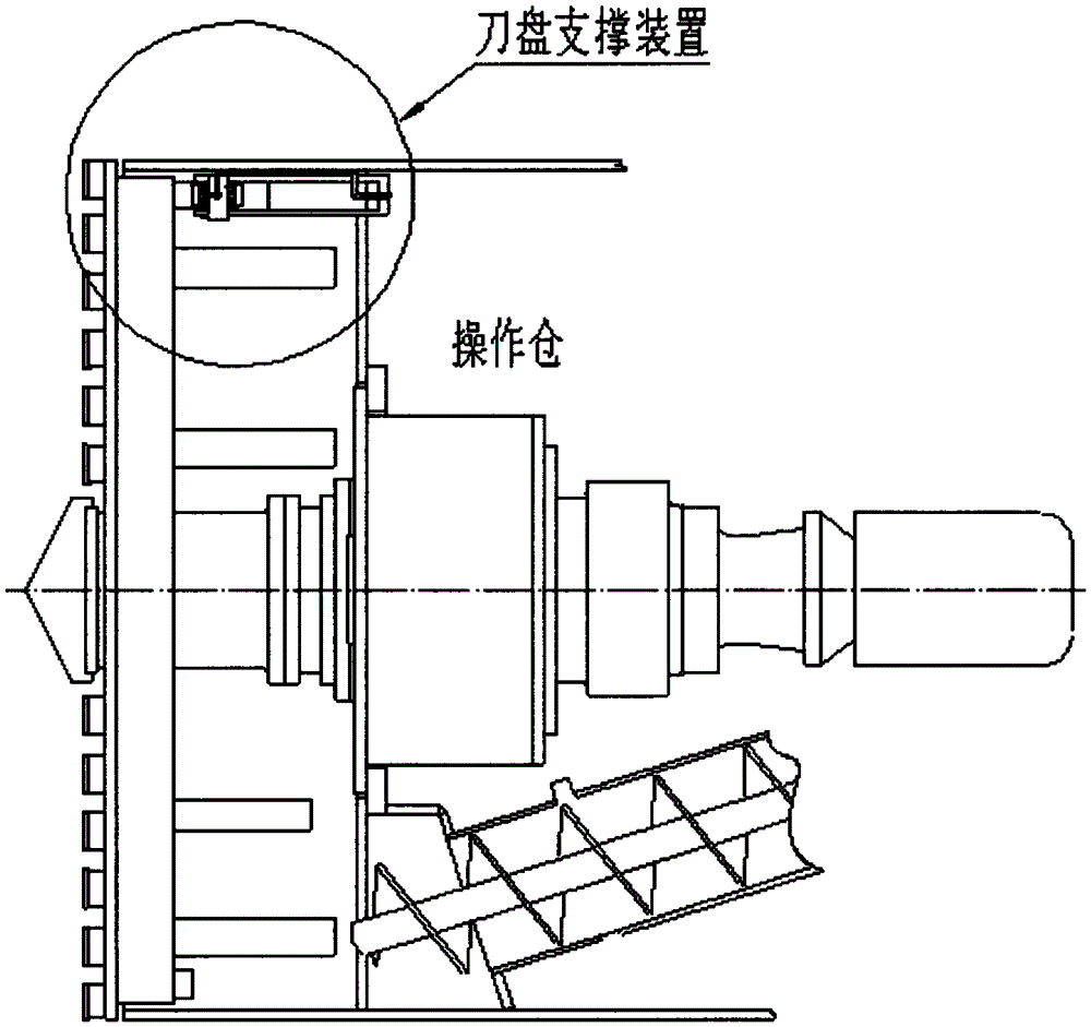
[0018] Such as figure 1 As shown: the cutterhead supporting device provided by the present invention needs to be provided with a circular track 1 behind the cutterhead, and several cutterhead supporting devices are respectively arranged along the circumference on the partition plate of the roadheader to support the cutterhead.

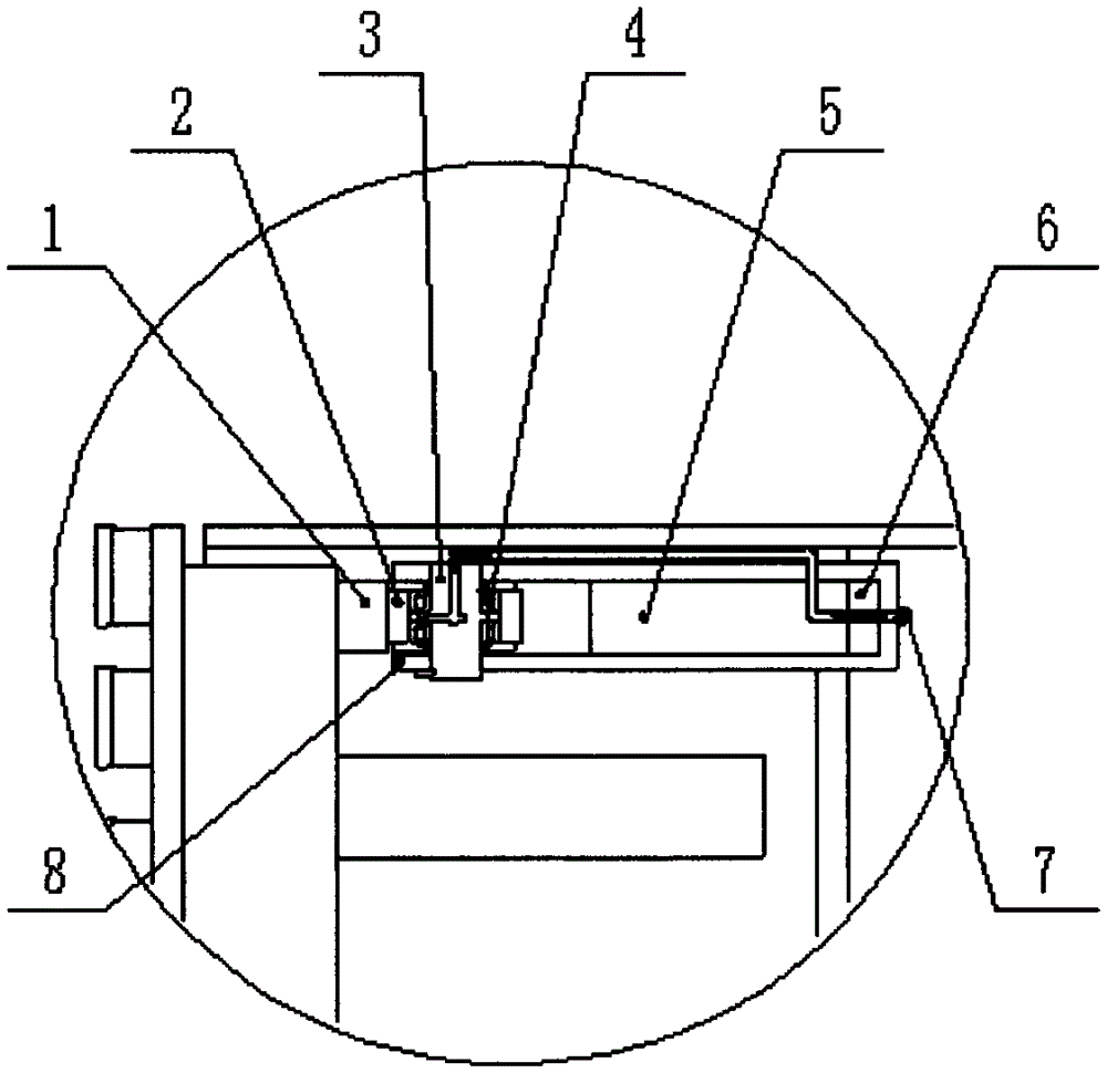
[0019] Such as figure 2 Shown: the cutter head supporting device provided by the present invention is composed of roller 2, roller shaft 3, bearing 4, bracket 5, inclined iron 6, oil nozzle 7, clamping plate 8 and circular track 1.

[0020] The roller 2 is supported on the roller shaft 3 by the bearing 4, and the roller shaft 3 is installed on the support 5 and fixed by the clamping plate 8.

[0021] The support 5 passes through the dividing plate of the working chamber of the roadheader and is fixed by the wedge iron 6 .

[0022] A lubricating oil path is provided on the support 5, and when the roadheader is working, oil can be supplied to the bear...


PUM


Abstract

The invention provides a cutterhead supporting device. A plurality of cutterhead supporting units are arranged inside a heading machine to bear the rock-soil pressure. In this way, the additional bending moment applied on a cutterhead is reduced, and the expense in purchasing large bearings is reduced. Meanwhile, the device is convenient to install, repair and replace.

Description

technical field [0001] The invention relates to a cutter head supporting device, which is suitable for the design and manufacture of a boring machine. Background technique [0002] Existing roadheaders are all provided with a cutterhead conforming to the diameter of the built tunnel, and on the cutterhead surface facing the shaft surface on the cutterhead, several fixed or freely rotating cutters are housed. Immediately behind the cutter head, there is a cylinder as the casing of the roadheader. In the center of the cylinder, a shaft that can rotate around the tunnel axis is supported by bearings. The front end of the rotating shaft is connected with the cutterhead, and the rear part is connected with the gear and the motor. The power of the motor drives the rotating shaft through the gear, drives the cutter head to rotate, and then cuts the rock and soil through the cutter on the cutter head. [0003] The tunnel boring machine designed with this method has the cover type ...

Claims


Application Information

Patent Timeline
Patent Type & Authority Applications(China)
IPC IPC(8): E21D9/10
CPCE21D9/1093
Inventor 葛维民张银生华群王华薛晓
Owner 江苏银旭隧道机械有限公司
Learn More