Shift registering unit, shift register, driving method of shift register and display device

A shift register unit, potential technology, applied in static memory, digital memory information, instruments, etc., can solve the problems of large number of transistors, high power consumption of driving circuit, node potential competition, etc., to reduce power consumption and enhance stability. , to avoid the effect of node potential competition

Active Publication Date: 2016-03-16
WUHAN TIANMA MICRO ELECTRONICS CO LTD +1
View PDF7 Cites 37 Cited by
  • Summary
  • Abstract
  • Description
  • Claims
  • Application Information

AI Technical Summary

Problems solved by technology

[0005] Both of the above two existing designs have the problem of node potential competition...

Method used


Image

  • Shift registering unit, shift register, driving method of shift register and display device
  • Shift registering unit, shift register, driving method of shift register and display device
  • Shift registering unit, shift register, driving method of shift register and display device

Examples


Embodiment Construction

[0023] The application will be further described in detail below in conjunction with the accompanying drawings and embodiments. It should be understood that the specific embodiments described here are only used to explain related inventions, rather than to limit the invention. It should also be noted that, for the convenience of description, only the parts related to the related invention are shown in the drawings.

[0024] It should be noted that, in the case of no conflict, the embodiments in the present application and the features in the embodiments can be combined with each other. The present application will be described in detail below with reference to the accompanying drawings and embodiments.

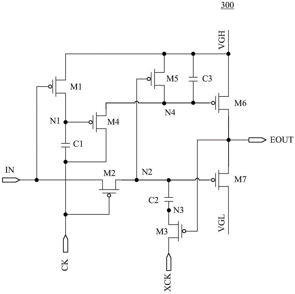
[0025] Please refer to image 3 , which shows a schematic circuit structure diagram of the first specific embodiment of the shift register unit provided by the present application. like image 3 As shown, the shift register unit 300 includes a first transistor M1, a second...


PUM


Abstract

The invention discloses a shift registering unit, a shift register, a driving method of the shift register and a display device. The shift registering unit comprises a first transistor, a second transistor, a third transistor, a fourth transistor, a fifth transistor, a sixth transistor, a seventh transistor, a first capacitor, a second capacitor, a third capacitor, an input signal end, a first clock signal end, a second clock signal end, a first voltage signal end, a second voltage signal end and a first output end. According to the invention, shift output of grid signals can be achieved via quite few transistors, power consumption of the shift register is reduced; a circuit failure caused by potential competence of nodes and threshold value drifting of the transistors can be avoided; and stability of circuit operation is enhanced.

Description

technical field [0001] The present application relates to the field of display technology, in particular to a shift register unit, a shift register and a driving method thereof, and a display device. Background technique [0002] In a conventional design of a display panel, a pixel array, a plurality of gate lines, and a data line insulated and intersecting with the plurality of gate lines may be arranged on the display panel. In addition, a gate driving circuit may also be arranged on the display panel. After the gate drive circuit shifts the input single pulse signal step by step, each gate line is turned on in turn to realize the row scanning of the pixel array on the display panel. [0003] figure 1 A schematic structural diagram of a driving unit of an existing gate driving circuit is shown, and the driving unit is used to drive a gate line. like figure 1 As shown, the driving unit 100 includes a shift register unit 11 and an inverter 12 . The shift register unit 1...

Claims


Application Information

Patent Timeline
IPC IPC(8): G09G3/20
CPCG09G3/20G11C19/28G09G2310/0286
Inventor 李玥邹文晖钱栋
Owner WUHAN TIANMA MICRO ELECTRONICS CO LTD
Why Eureka
Try Eureka