
Single-winding bearingless motor torque and suspension force direct controller and construction method
A bearingless motor and suspension force technology, which is applied in the direction of motor generator control, electronic commutation motor control, electromechanical brake control, etc., can solve the problems of current fluctuation, complicated switching tube control process, and large power loss.
- Summary
- Abstract
- Description
- Claims
- Application Information
AI Technical Summary
Problems solved by technology
Method used
Image

Examples
Embodiment Construction
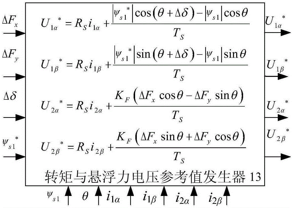
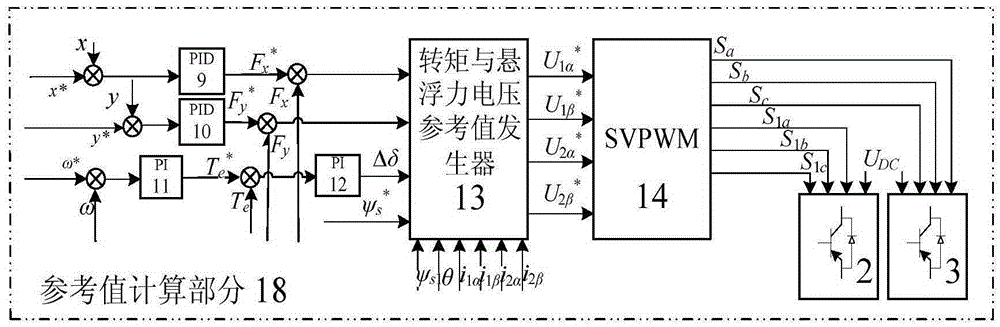
[0031] Figure 7 What is shown is a schematic diagram of the composition of the direct controller 20 of torque and levitation force of a complete single-winding double-three-phase bearingless permanent magnet motor. The torque and suspension force direct controller 20 is composed of a reference value calculation part 18 and an observed value calculation part 19 .
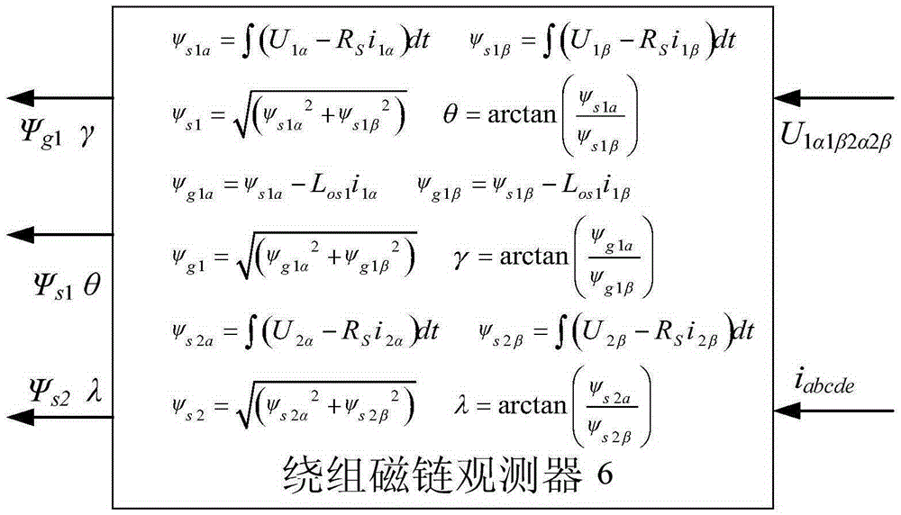
[0032] The observed value calculation part 19 is composed of a winding flux observer 6, a levitation force observer 7, a torque observer 8 and two matrix transformation modules 4, 5, wherein the output of the matrix transformation module 4 is connected to the winding flux linkage The input of the observer 6 and the output of the winding flux observer 6 are respectively connected to the levitation force observer 7 and the torque observer 8, and the output of the matrix transformation module 5 is respectively connected to the winding flux observer 6 and the torque observer 8. Suspension force observer 7 respectively ...
PUM
 Abstract
Description
Claims
Application Information