
Floating photovoltaic power generation system with adaptive photovoltaic tracking performance

A photovoltaic power generation system, a floating technology, applied in the direction of photovoltaic power generation, the support structure of photovoltaic modules, photovoltaic modules, etc., can solve the problems of multiple reliability of devices, complex installation and debugging, photovoltaic control design problems, etc., to achieve easy handling and assembly , the effect of strong integration

Active Publication Date: 2017-11-17
陈秋菊
View PDF2 Cites 0 Cited by
  • Summary
  • Abstract
  • Description
  • Claims
  • Application Information

AI Technical Summary

Problems solved by technology

Since the above two photovoltaic tracking control structures have been in use, although they have the advantages of high tracking accuracy and convenient remote communication control, they also have disadvantages such as complex control links, complicated installation and debugging, many devices and low reliability, which poses a challenge to the actual photovoltaic control design. bring trouble

Method used


Image

  • Floating photovoltaic power generation system with adaptive photovoltaic tracking performance
  • Floating photovoltaic power generation system with adaptive photovoltaic tracking performance
  • Floating photovoltaic power generation system with adaptive photovoltaic tracking performance

Examples


Embodiment Construction

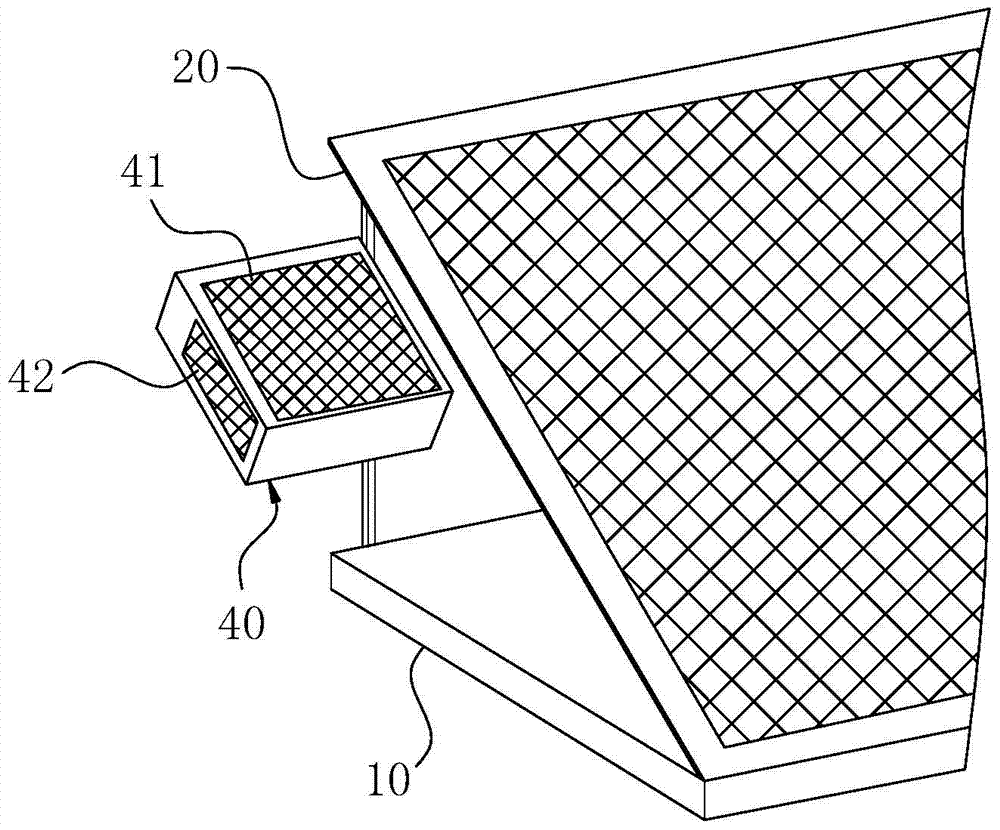
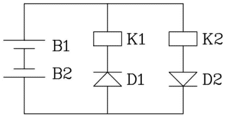
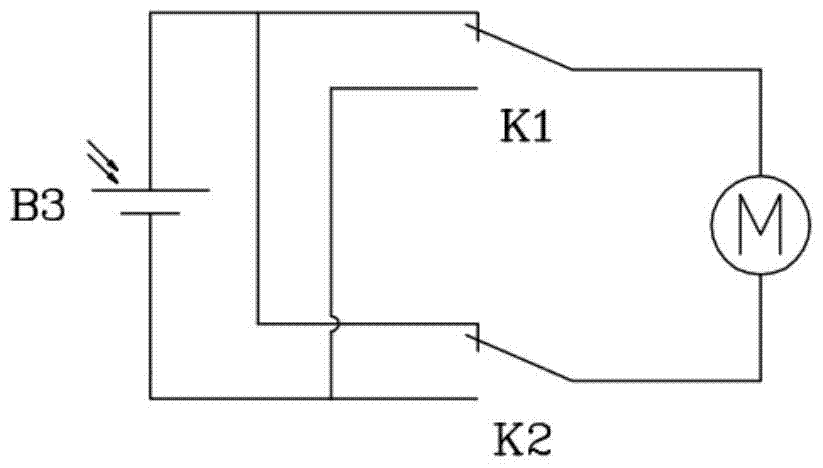
[0035] For ease of understanding, combined here Figure 1-10 One of the implementation structures of the present invention and its workflow are further described as follows:

[0036] The entire circuit control and driving structure of the present invention can be integrated in the control box 40 in the shape of a square box. The airtight inner cavity of the control box 40 is used for arranging lines, and the outer surface of the box body takes three adjacent surfaces to install the main photovoltaic panel 41 , the left photovoltaic panel 42 and the right photovoltaic panel. Specifically, as shown in 1, a relatively high-power main photovoltaic panel 41 is installed on the front side of the control box 40 parallel to and in the same direction as the light-receiving side panel surface of the solar panel 20, and two panels are installed on the left and right sides of the control box 40 respectively. Low power left photovoltaic panel 42 and right photovoltaic panel. The control ...


PUM


Abstract

The invention belongs to the field of the photovoltaic power generation of a solar cell panel, and particularly relates to a floating type photovoltaic power generation system with adaptive photovoltaic tracking performance. The floating type photovoltaic power generation system comprises a floating substrate, the solar cell panel and a direct current driving motor, wherein two ends of the direct current driving motor are independently connected with a relay switch K1 and a relay switch K2 in series; the two relay switches are communicated with the same electrode of a main cell when the coils of two relays synchronously lose power, and are both communicated with the other electrode of the main cell when the coils of two relays synchronously obtain power; a series-opposing cell set, the relay k1 and the relay K2 are mutually connected in parallel; the relay K1 and the relay k2 are both time-delay action relays; a parallel branch where the relay K1 is positioned is connected with a diode D1 in series, a parallel branch where the relay k2 is positioned is connected with a diode D2 in series, and the serial connection cut-off directions of the diode D1 and the diode D2 are mutually opposite. The floating type photovoltaic power generation system synchronously realizes the accurate action responsiveness of a sunlight irradiation angle to guarantee high-efficiency solar photovoltaic power generation requirements.

Description

technical field [0001] The invention belongs to the field of photovoltaic power generation based on solar panels, and in particular relates to a floating photovoltaic power generation system with adaptive photovoltaic tracking performance. Background technique [0002] Due to the rotation and revolution of the earth, the angle of the sun's light is changing all the time in spring, summer, autumn and winter, and every day when the sun rises and sets. Whether it is a land-based or floating solar photovoltaic power generation system, people hope that the solar power generation panels can face the sun at all times to achieve maximum power generation efficiency; especially for floating solar photovoltaic power generation systems Accurate and efficient sun light tracking is always a difficult problem to be solved. The photovoltaic tracking control system is an existing power control structure that can keep the solar panel facing the sun at all times, and make the sunlight shine v...

Claims


Application Information

Patent Timeline
Patent Type & Authority Patents(China)
IPC IPC(8): H02S20/32H02S40/34
CPCH02S20/00H02S40/00Y02E10/50
Inventor 陈秋菊
Owner 陈秋菊
Learn More