Receiver and manufacturing method

A receiver and shell technology, which is applied in the manufacture/assembly of earphones, receivers/earphone accessories, etc., can solve the problems of simplifying the manufacturing process and unfavorable receivers, and achieve the effects of simplifying the manufacturing process, reducing volume, and simplifying the structure

Active Publication Date: 2016-03-16
SUZHOU YICHUAN TECH CO LTD
View PDF4 Cites 6 Cited by
  • Summary
  • Abstract
  • Description
  • Claims
  • Application Information

AI Technical Summary

Problems solved by technology

[0004] Therefore, the technical problem to be solved by the present invention is to overcome the defect that the structure of the receiver in the prior art is not conducive to simplifying the manufacturing process

Method used


Image

  • Receiver and manufacturing method
  • Receiver and manufacturing method
  • Receiver and manufacturing method

Examples


Embodiment 1

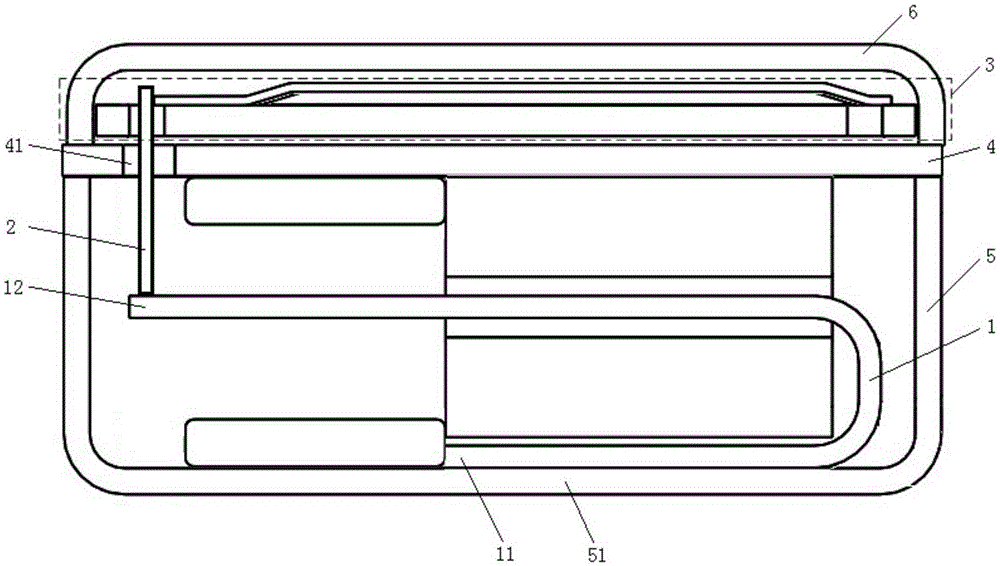
[0046] This embodiment provides a receiver, such as figure 1 As shown, it includes a U-shaped balanced armature 1 , a power transmission rod 2 , a diaphragm mechanism 3 , a middle-layer partition 4 , a lower shell 5 and an upper shell 6 .

[0047] The upper surface of the middle-layer partition 4 is sealedly connected with the upper shell 6 of the outer shell, and the lower surface of the middle-layer partition 4 is sealed with the lower shell 5 of the outer shell; Closed loop, can also be used as the iron core in the magnetic drive mechanism. Preferably, the materials of the above-mentioned middle-layer separator 4 and the lower shell 5 are soft magnetic materials, such as silicon steel sheet, soft ferrite, amorphous alloy, permalloy and other materials.

[0048] The U-shaped balance armature 1 includes two parallel arms. The first parallel arm 11 is fixedly connected to the bottom 51 of the lower shell 5 of the outer shell. The second parallel arm 12 of the U-shaped balance...

Embodiment 2

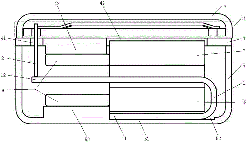
[0062] This embodiment provides a receiver, such as image 3 As shown, it includes a U-shaped balanced armature 1 , a power transmission rod 2 , a diaphragm mechanism 3 , a middle-layer partition 4 , a lower shell 5 and an upper shell 6 .

[0063] The upper surface of the middle-layer partition 4 is sealedly connected with the upper shell 6 of the outer shell, and the lower surface of the middle-layer partition 4 is sealed with the lower shell 5 of the outer shell; Closed loop, can also be used as the iron core in the magnetic drive mechanism.

[0064] The U-shaped balance armature 1 includes two parallel arms, the first parallel arm 11 is fixedly connected to the middle partition 4 , and the second parallel arm 12 of the U-shaped balance armature 1 is suspended in the middle partition 4 and the lower shell 5 of the outer shell. The enclosed first hollow cavity.

[0065] The diaphragm mechanism 3 is located in the second hollow cavity enclosed by the middle-layer partition p...

Embodiment 3

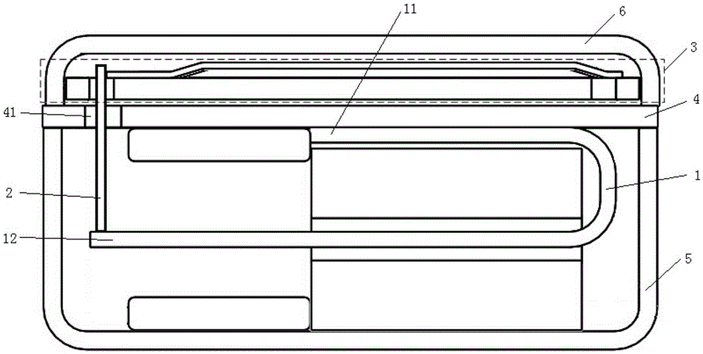
[0074] This embodiment provides a method for making a receiver, and the method is applied to, for example, making a receiver such as figure 1 and 2 receivers shown, such as Image 6 As shown, the method includes the following steps:

[0075] S1, including:

[0076] S1-1: Position and install the first parallel arm 11 of the U-shaped balance armature 1 on the bottom 51 of the lower casing 5 of the outer casing.

[0077] S1-2: Then, one end of the power transmission rod 2 is positioned and installed on the end of the second parallel arm 12 of the U-shaped balance armature 1 .

[0078] S1-3: Then, cover the opening of the lower shell 5 with the middle-layer partition 4, and seal the connection with the lower shell 5 of the outer shell.

[0079] S1-4: The lower part of the receiver is then finished.

[0080] S2, including:

[0081] S2-1: Position and install the diaphragm mechanism 3 in the upper casing 6 of the outer casing.

[0082] S2-2: The fabrication of the upper part...


PUM


Abstract

The invention discloses a receiver and a manufacturing method, wherein the receiver comprises a U-shaped balanced armature, a power transmission rod, a vibration diaphragm mechanism, a middle clapboard, an outer lower shell and an outer upper shell; the upper surface of the middle clapboard and the outer upper shell are in sealed connection; the lower surface of the middle clapboard and the outer lower shellare in sealed connection; the middle clapboard and the outer lower shell are used for providing a flux path; the first parallel arm of the U-shaped balanced armature is fixedly connected with the bottom of the outer lower shell; the second parallel arm of the U-shaped balanced armature is hung in the air and positioned in a first hollow cavity formed by the middle clapboard and the outer lower shell in an encircling manner; the vibration diaphragm mechanism is positioned in a second hollow cavity formed by the middle clapboard and the outer upper shell in an encircling manner; the power transmission rod passes through a first through hole on the middle clapboard; one end of the power transmission rod is connected with the second parallel arm of the U-shaped balanced armature; and the other end of the power transmission rod is connected with the vibration diaphragm mechanism. The receiver provided by the invention is simple in structure and small in volume; and the manufacturing process can be simplified easily.

Description

technical field [0001] The invention relates to the technical field of micro-miniature device design, in particular to a receiver and a manufacturing method. Background technique [0002] The receiver is widely used in portable electronic devices such as mobile phones, notebook computers, hearing aids, etc., and is a micro-miniature device. In the production of this kind of micro-miniature device, simplifying the production process is the goal pursued by many manufacturers. After the production process is simplified, it can not only save production costs and improve product competitiveness, but also shorten product production time and increase annual output. . The design of the manufacturing process is largely based on the structure design of the micro-miniature device itself. Therefore, optimizing the structure design and manufacturing process design of the receiver is an urgent problem to be solved by the current receiver manufacturers. [0003] At present, the commonly ...

Claims


Application Information

Patent Timeline
Patent Type & Authority Applications(China)
IPC IPC(8): H04R1/10
CPCH04R1/1058
Inventor 张晋良
Owner SUZHOU YICHUAN TECH CO LTD
Why Eureka
Try Eureka