Roller frame, automatic spinning equipment and the application of the equipment

A technology of spinning equipment and roller frame, which is applied in the field of spinning equipment, can solve the problems of blackened spinning of collar parts, product scrapping, difficulties, etc., and achieve the effect of reducing frictional resistance

Active Publication Date: 2019-01-29
ZHUZHOU ELITE ELECTRO MECHANICAL
View PDF7 Cites 0 Cited by
  • Summary
  • Abstract
  • Description
  • Claims
  • Application Information

AI Technical Summary

Problems solved by technology

[0003] When the spinning equipment is used to spin the collar on the gear shaft of the casing of the column power steering gear, if the elastic bush cannot effectively hold the gear shaft, it will slip every time it is spinning, and the gear will The shaft is scratched and the product is scrapped; during spinning, if the frictional heat of the rolling wheel is high, not only the collar parts will be burned black, but also the surface itself will be welded due to heat source metal penetration to form uneven spots, which will make the spinning more difficult

Method used


Image

  • Roller frame, automatic spinning equipment and the application of the equipment
  • Roller frame, automatic spinning equipment and the application of the equipment
  • Roller frame, automatic spinning equipment and the application of the equipment

Examples


Embodiment 1

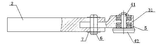
[0037] This embodiment provides a roller frame, such as image 3 and Figure 4 As shown, the roller frame 3 is a "Y"-shaped structure with two symmetrical protrusions 31, and angular contact bearings 5 ​​and rolling wheels 4 are respectively installed in the protrusions 31; the rolling wheels 4 include rollers 41 and roller 42; the angular contact bearing 5 is installed in the roller frame 3, the rolling wheel 4 is installed in the inner hole of the angular contact bearing 5, and the roller 42 extends out of the roller frame 3.

[0038]Two angular contact bearings 5 ​​are installed in each of the protrusions 31 .

[0039] Each of the angular contact bearings 5 ​​can move up and down along the axis of rotation of the workpiece in the roller frame 3, and the setting of the movement gap is less than 0.03mm.

[0040] During spinning, the two rolling wheels 4 are symmetrical with respect to the rotation axis of the workpiece, and the axis of the roller 41 deviates from the rotati...

Embodiment 2

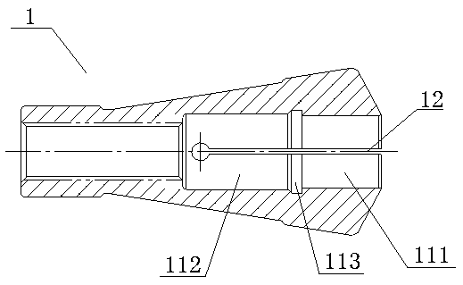
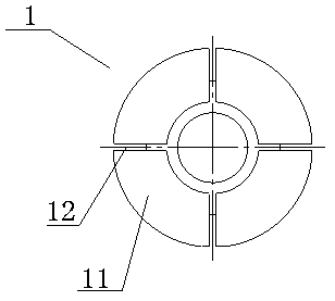
[0043] This embodiment provides an automatic spinning equipment, such as Figure 1~5 As shown, the spinning equipment includes an elastic bushing 1, a knife seat, a knife bar 2, a roller frame 3 and a rolling wheel 4 described in Embodiment 1; the elastic bushing 1 includes a blade 11, and the blade 11 An elastic groove 12 is arranged between them, and a clamping hole 111, an elastic cavity 112, and a transition zone 113 connecting the clamping hole 111 and the elastic cavity 112 are opened in the blade 11; the rolling wheel 4 includes a roller 41 and a roller 42 ; One end of the knife bar 2 is connected with the knife seat, and the other end of the knife bar 2 is connected with a roller frame 3; Angular contact bearing 5 and described rolling wheel 4 are installed respectively; Described angular contact bearing 5 is installed in the roller frame 3, as figure 2 and Figure 5 as shown, Figure 5 Among them, 8 is a bearing installation hole, and 9 is a pin installation hole;...

Embodiment 3

[0058] This embodiment provides a preferred application of the automatic spinning equipment described in the present invention. This embodiment uses the automatic spinning equipment described in the embodiment to spin the collar on the gear shaft of the casing in the column power steering gear on, such as Figure 6 The schematic diagram of the combined structure of the middle shell is shown. Figure 6 Among them, the middle housing assembly includes the middle housing 100, the bearing 101, the collar 102 and the gear shaft 103. The spinning equipment of the present invention can solve the problem of the middle housing assembly, and the bearing 101 tightly clamps the gear shaft 103. It lives on the installation end face of the middle casing 100, so that the gear shaft combination is in the working state, and there is no axial movement and dislocation between the gear shaft and the middle casing 100, so as to avoid abnormal noise and failure of the column booster. The spinning ...


PUM


Abstract

The invention provides a roller carrier, automatic spinning equipment and an application thereof. The roller carrier is of a Y-shaped structure with two symmetrical bulges, wherein bearings and rolling wheels are installed in each bulge respectively; each rolling wheel comprises a rolling shaft and a roller; and each bearing is installed in the roller carrier, each rolling wheel is installed in an inner hole of the corresponding bearing, and each roller stretches out of the roller carrier. The spinning equipment comprises an elastic bushing, a tool apron, a tool rod and said roller carrier, wherein one end of the tool rod is connected with the tool apron, and the other end of the tool rod is connected with the roller carrier; and the roller carrier is movably connected with the tool rod through a connection rod, and the tool rod is capable of horizontally swinging around the connection rod. According to the invention, the structure of the roller carrier, and the physical and mechanical properties of the elastic bushing or the material of the rolling wheels are creatively improved, so that a friction resistance between each rolling wheel and a workpiece is far less than a clamping torque of the elastic bushing on the workpiece during machining; and the phenomenon of forming moundy bulges on extrusion wheels by plastic slip and fusion welding of heat-source metals due to high friction force and high friction heat in the prior art is completely overcome.

Description

technical field [0001] The invention relates to the technical field of spinning equipment, and more particularly, to a roller stand, automatic spinning equipment and applications of the equipment. Background technique [0002] The engineering capability of the spinning system is the core of the spinning equipment, and it is also the first criterion for judging whether the equipment can successfully spin out qualified workpieces. When the friction resistance of the rolling wheel of the spinning equipment is close to the clamping torque of the elastic bushing on the workpiece, the engineering capability of the spinning equipment is in an unstable state, that is, the clamping torque of the elastic bushing on the workpiece is equal to the total of the spinning torque. When the friction resistance is equal or lower, the workpiece and the elastic bushing will slip during spinning, causing the parts to be damaged and scrapped. [0003] When the spinning equipment is used to spin t...

Claims


Application Information

Patent Timeline
Patent Type & Authority Patents(China)
IPC IPC(8): B21D22/14
CPCB21D22/14
Inventor 尹乐军李澎宋新华
Owner ZHUZHOU ELITE ELECTRO MECHANICAL
Why Eureka
Try Eureka