Composite spinning forming device and process for clutch shell with internal longitudinal teeth

A clutch housing and composite spinning technology, which is applied in the field of composite spinning forming equipment and technology for inner longitudinal gear clutch housings, can solve the problems of low processing efficiency and material utilization, inability to realize non-penetrating gear processing, and fatigue impact resistance Weak performance and other problems, to achieve the effect of high material utilization, strong flexibility, and low tonnage requirements

Active Publication Date: 2016-03-23
SICHUAN AEROSPACE LONG MARCH EQUIP MFG CO LTD
View PDF5 Cites 13 Cited by
  • Summary
  • Abstract
  • Description
  • Claims
  • Application Information

AI Technical Summary

Problems solved by technology

Cutting is done by gear hobbing, broaching, etc., the processing efficiency and material utilization rate are low, the material fiber streamline is cut off, the fatigue impact resistance is weak, and the processing of non-penetrating teeth cannot be realized
Forging extrusion molding requires high equipment tonnage, and usually needs to heat the billet, resulting in high energy consumption
In addition, the forging extrusion molding die bears high extrusion strength and short service life

Method used


Image

  • Composite spinning forming device and process for clutch shell with internal longitudinal teeth
  • Composite spinning forming device and process for clutch shell with internal longitudinal teeth
  • Composite spinning forming device and process for clutch shell with internal longitudinal teeth

Examples


Embodiment 1

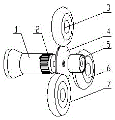
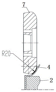
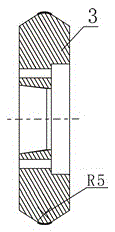
[0026] Embodiment 1: see Figure 1 to Figure 5 , a composite spinning forming equipment for a clutch housing with internal longitudinal teeth, comprising a main shaft 1, a mandrel 2, and a tail top 5 arranged coaxially in sequence, one end of the mandrel 2 is installed on the main shaft 1, and the other end is provided with The positioning shaft of the blank 4 is installed, and the outer wall of the mandrel 2 is uniformly distributed with outer longitudinal teeth along the axial direction. The mandrel 2 is provided with end face teeth on one end of the positioning shaft, and the middle part of the tail top 5 is provided with a through hole, through the through hole and The positioning shaft is detachably connected; the first rotary wheel 7, the second rotary wheel 3 and the third rotary wheel 6 are arranged on the outer side of the tail top 5, and the rotary axes of the three rotary wheels are set along the axial direction of the main shaft 1, and can be connected with the main...


PUM


Abstract

The invention discloses a composite spinning forming device for a clutch shell with internal longitudinal teeth. The device comprises a spindle, a mandrel and a tailstock, wherein the spindle, the mandrel and the tailstock are coaxially arranged in sequence. One end of the mandrel is mounted on the spindle, and a positioning shaft for mounting a blank is arranged at the other end of the mandrel; external longitudinal teeth are evenly distributed on the outer wall of the mandrel in the axial direction, and end face teeth are further arranged on the end face of the end, provided with the positioning shaft, of the mandrel; a through hole is formed in the middle of the tailstock, and the tailstock is detachably connected with the positioning shaft through the through hole; a first spinning wheel, a second spinning wheel and a third spinning wheel are arranged on the outer side of the tailstock, spinning wheel rotation axes of the three spinning wheels are arranged in the direction of the axis of the spindle and can form included angles of 0-90 degrees with the axis of the spindle, and the three spinning wheels can be linked for feeding in the direction of the rotation axes and the radial direction. By means of the device, the machining efficiency of the clutch shell with the internal longitudinal teeth can be improved. The composite spinning forming device is mounted on power spinning equipment, different working molded surfaces are designed for the three spinning wheels, and certain included angles are formed between the rotation axes and the axis of the spindle, so that common spinning, power spinning and extrusion functions are achieved respectively.

Description

technical field [0001] The invention relates to spinning forming equipment and technology, in particular to a compound spinning forming equipment and technology for a clutch housing with inner longitudinal teeth. Background technique [0002] After several years of continuous high-speed blowout development, the domestic automobile industry has entered a relatively stable period, and the current production and sales scale is maintained at about 20 million vehicles. The huge automobile market also has a huge demand for gearbox clutches. The gearbox clutch is composed of a clutch housing, a friction plate, a steel plate, etc., and the connection and disconnection of the torque are realized through the compression and release of the friction plate. The clutch housing is one of the core parts of the clutch, and the clutch housing and the friction plate usually mesh with each other through tooth shapes. The clutch housing usually has internal longitudinal teeth, external longitu...

Claims


Application Information

Patent Timeline
Patent Type & Authority Applications(China)
IPC IPC(8): B21D22/16
CPCB21D22/16
Inventor 李志远王立志侯春林崔旭昌康权
Owner SICHUAN AEROSPACE LONG MARCH EQUIP MFG CO LTD
Why Eureka
Try Eureka