

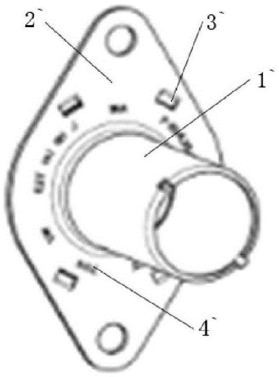
Cylindrical drawn part production and machining equipment
A processing equipment and cylindrical technology, which is applied in the field of cylindrical drawing parts production and processing equipment, can solve the problems of difficult discharge of waste, low production efficiency, and process stoppage.
- Summary
- Abstract
- Description
- Claims
- Application Information
AI Technical Summary
Problems solved by technology
Method used
Image

Examples
Embodiment Construction
[0019] The production and processing equipment for tubular stretched parts of the present invention will be further described in detail in conjunction with the accompanying drawings and specific embodiments.
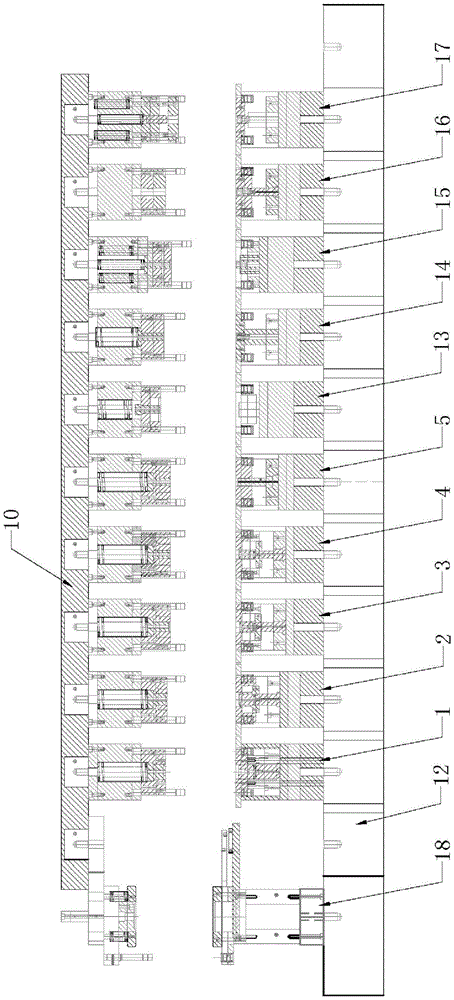
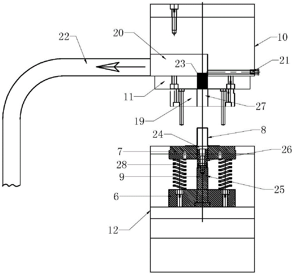
[0020] As shown in the figure, the production and processing equipment for cylindrical stretched parts of the present invention includes an upper mold base 10 and a lower mold base 12 matched with the upper mold base. The upper mold base 10 and the lower mold base 12 have A plurality of stretching dies, said stretching dies are arranged in sequence along the process direction as one stretching die 1, two stretching dies 2, three stretching dies 3, four stretching dies 4, stretching dies Type mold 5; Also comprise trimming punching die 13, typing die 14, punching die 15, punching top hole die 16 and punching claw die 17 that are arranged in sequence in stretching shaping die 5 rears, the front side of stretching die 1 together Also be provided with blanking die 18, stretc...
PUM
 Abstract
Description
Claims
Application Information