
Pneumatic rivet tool

A tool and rivet technology, applied in the field of pneumatic rivet tools, can solve the problems of complex structure, heavy pollution and high cost, and achieve the effects of low noise, energy saving and light weight

Active Publication Date: 2016-03-23
昆山铆足劲工具有限公司
View PDF7 Cites 6 Cited by
  • Summary
  • Abstract
  • Description
  • Claims
  • Application Information

AI Technical Summary

Problems solved by technology

[0003] In the self-priming rivet tool of the prior art, since there must be a negative pressure in the opposite direction of the riveting of the gun head when sucking the nail, the expensive compressed air must be transported to the opposite direction of the gun head all the time, resulting in a large waste of tools and high noise
Tool riveting is controlled by the auxiliary air circuit, which has a complex structure and high cost
At present, the low-end pneumatic rivet tool switching valve is currently the mainstream control device. There is usually a lever at the lower end before shaking hands. Although the price is low, the lever has reciprocating movement when used, which may cause hand injury. Moreover, the exhaust gas from riveting is polluted and noisy.

Method used


Image

  • Pneumatic rivet tool
  • Pneumatic rivet tool
  • Pneumatic rivet tool

Examples


Embodiment Construction

[0028] The present invention will be further described below in conjunction with accompanying drawing;

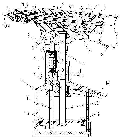
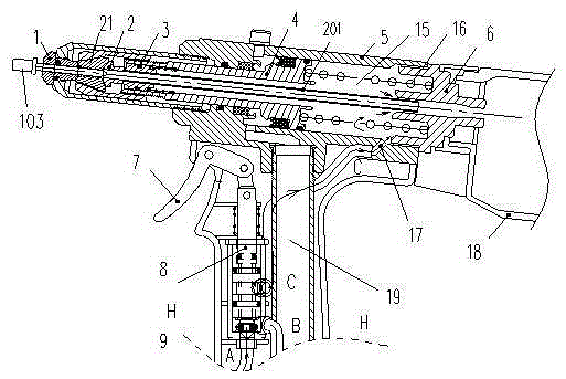
[0029] Such as Figure 1 to Figure 8 As shown, a pneumatic rivet tool includes a self-locking gun head 1, a top core assembly 2, an oil cylinder assembly, a switch trigger 7, a handle shell 9 and a valve body assembly 8;

[0030] The cylinder assembly is provided with a top core assembly 2, and the front end of the top core assembly 2 is connected to the self-locking gun head 1 through three claws 21; a handle shell 9 is fixed below the cylinder assembly;

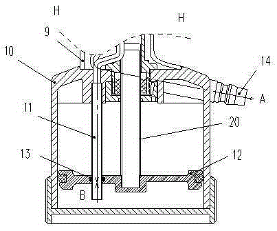
[0031] The handle shell 9 is provided with a valve body assembly 8, a switch trigger 7 for controlling the opening and closing of the valve body assembly, and a hydraulic oil chamber 19; the lower end of the handle shell 9 is provided with an air cylinder body 10, and a piston 12 is arranged inside the air cylinder body 10 And connecting the communication hole 804 on the side of the valve body assembly 8 and the ventila...


PUM


Abstract

The invention relates to a pneumatic rivet tool. The pneumatic rivet tool comprises a self-locking gun head, a mandrel-pushing assembly, an oil cylinder assembly, a switch trigger, a handle housing and a valve body assembly, wherein the mandrel-pushing assembly is arranged in the oil cylinder assembly, and the front end of the mandrel-pushing assembly is connected with the self-locking gun head through a three-jaw; the handle housing is fixed below the oil cylinder assembly; the valve body assembly, the switch trigger for controlling opening and closing of the valve body assembly, and a hydraulic oil cavity are arranged in the handle housing; an air cylinder body is arranged at the lower end of the handle housing, and a piston, and a ventilation guide tube connecting a communication hole in the side surface of the valve body assembly with the piston, are arranged in the air cylinder body; a piston rod connected with a hydraulic oil cavity is arranged on the piston; and an intake connector connected to the lower end of the valve body assembly is further arranged on the air cylinder body. The tool is simple in structure, capable of realizing single-hand random-direction riveting, reasonably using a space in the handle housing, and cyclically utilizing waste gas after riveting, green and environment-friendly, energy-saving, low in noise, less in pollution, and capable of increasing working efficiency.

Description

technical field [0001] The invention belongs to the technical field of machinery, and in particular relates to a pneumatic riveting tool. Background technique [0002] Pneumatic rivet tools are currently one of the main operating tools in the riveting industry, including non-suction rivet tools and self-suction rivet tools. In any reverse riveting, there is no need to worry that the rivet will fall out of the gun head. Second, the waste nail rod will be automatically sucked into the nail collection tube after the riveting is completed. The user does not have to worry about the waste nail rod falling out of the gun head. The tool can be riveted with one hand. [0003] In the self-priming rivet tool of the prior art, there must be negative pressure in the opposite direction of the gun head riveting when sucking the nail, and expensive compressed air must be transported in the opposite direction of the gun head all the time, resulting in a large waste of tools and high noise. ...

Claims


Application Information

Patent Timeline
Patent Type & Authority Applications(China)
IPC IPC(8): B21J15/10B21J15/18B21J15/32
CPCB21J15/105B21J15/043B21J15/24B21J15/326B21J15/18B21J15/32
Inventor 洪劲松
Owner 昆山铆足劲工具有限公司
Learn More