Outside rear-view mirror and method for adjusting outside rear-view mirror when used for vehicle
A technology for exterior rearview mirrors and adjustment methods, applied to vehicle parts, optical observation devices, transportation and packaging, etc., can solve the problems of small curvature of rearview auxiliary mirrors, increase the viewing area, and misjudgment by drivers, so as to avoid Effects of visual difference, elimination of blind spots, and reduction of blind spots
- Summary
- Abstract
- Description
- Claims
- Application Information
AI Technical Summary
Problems solved by technology
Method used
Image
Examples
Embodiment 1
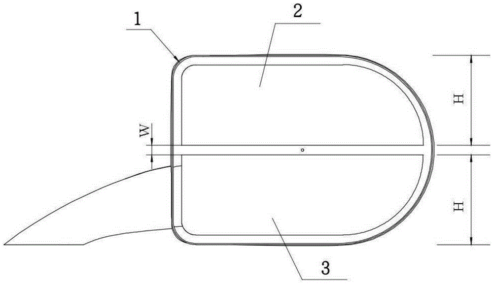
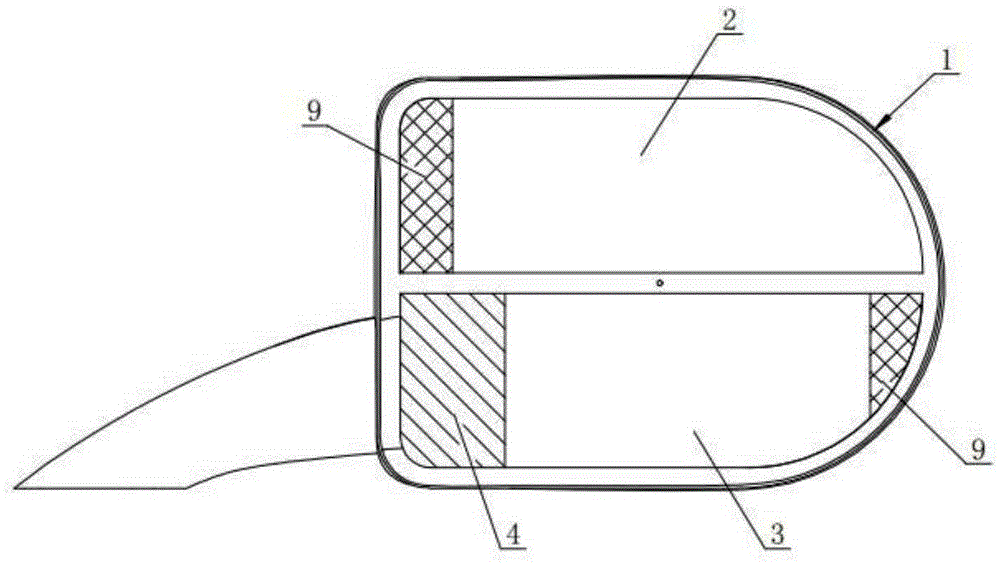
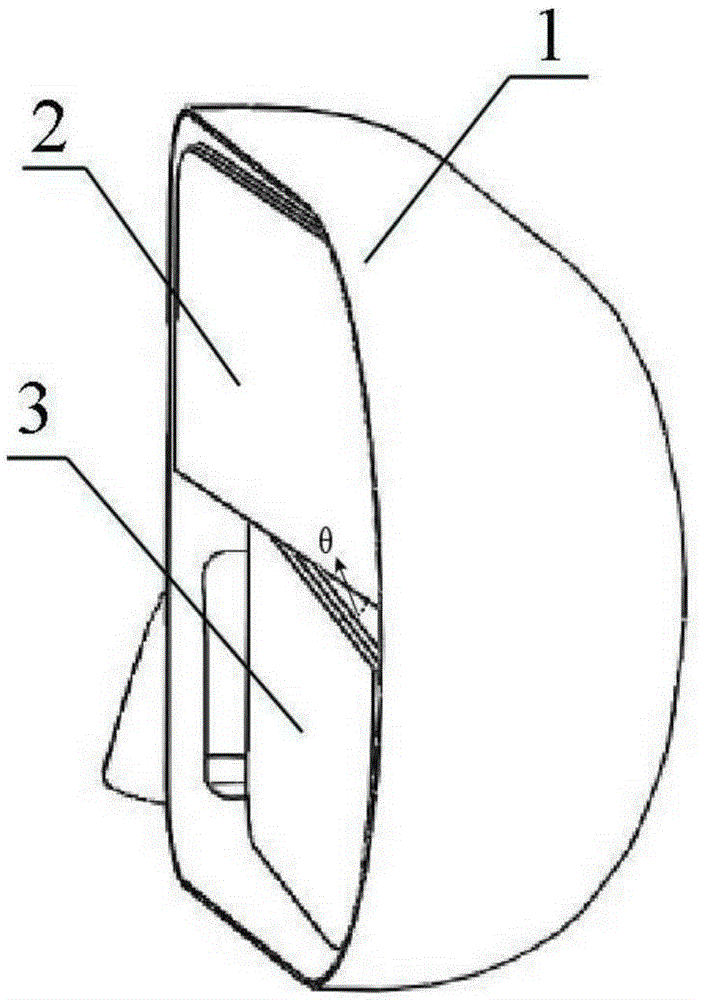
[0038] an exterior rearview mirror, such as figure 1 , image 3 , Figure 4 As shown, it includes a reflector group and a housing 1, the reflector group is composed of a first reflector 2 and a second reflector 3, and the first reflector 2 and the second reflector 3 are vertically arranged up and down In the housing 1, the housing 1 is one; the driving mechanism 6 is located in the cavity 8 formed between the mirror group and the housing 1, and is connected to the first mirror 2 and the second mirror 3 respectively. Connect and drive the first reflective mirror 2 and the second reflective mirror 3 to rotate in the housing 1; the first reflective mirror 2 and the second reflective mirror 3 are the most popular convex mirrors in conventional exterior rearview mirrors , the radius of curvature of the first reflective mirror 2 and the second reflective mirror 3 are the same.
[0039] The above-mentioned technical scheme is the core technical scheme of the present invention, and...
Embodiment 2
[0047] The vehicle uses the adjustment method of the exterior rearview mirror of the present invention.
[0048] Regarding the adjustment method of the second reflector located on the lower side in the present invention, we first determined the following adjustment principles during the test process. One is that the operation is convenient and reliable, and the other is that the body on both sides can be seen to basically meet the daily driving and reversing requirements. Under the premise of maximizing the angle of view that spreads out from both sides of the vehicle. After repeated tests and comparisons, we found that when the second reflector located on the lower side is adjusted left and right toward the vehicle body until one-fifth of the mirror surface shows the vehicle body, the above principles can be well satisfied at the same time.
[0049] Regarding the adjustment method of the first reflective mirror located on the upper side in the present invention, we first dete...
Embodiment 3
[0060] In the experimental test of exterior rearview mirror adjustment, the reference driver's seat is on the left side and the passenger seat is on the right side. Because the blind spot phenomenon on the side of the co-pilot's seat of the vehicle has a greater impact on the driver, this side of the experiment focuses on the comparative test of the conventional rearview mirror and the exterior rearview mirror of the present invention.
[0061] In this embodiment, a comparatively popular sedan car is used as a test car, such as Figure 5 Shown, A is the first reflective mirror on the upper right of the present invention; B is the second reflective mirror on the lower right of the present invention, and the conventional right rearview mirror. 3000mm.
[0062] Place several reference test vehicles at the rear of the vehicle flush to the right.
[0063] First test with the conventional right exterior rearview mirror, and adjust the reflector until one-fifth of the horizontal mi...
PUM
 Abstract
Description
Claims
Application Information
 - R&D
- Intellectual Property
- Life Sciences
- Materials
- Tech Scout
- Unparalleled Data Quality
- Higher Quality Content
- 60% Fewer Hallucinations
Browse by: Latest US Patents, China's latest patents, Technical Efficacy Thesaurus, Application Domain, Technology Topic, Popular Technical Reports.
© 2025 PatSnap. All rights reserved.Legal|Privacy policy|Modern Slavery Act Transparency Statement|Sitemap|About US| Contact US: help@patsnap.com


