Multi-interlayer detachable pin locking thread assembly for blind hole and locking method

A technology of threaded components and pins, applied in the directions of threaded fasteners, locking fasteners, screws, etc., can solve the problems of hidden safety hazards, poor safety reliability, and low flight safety factor of aerospace vehicles, and meet the requirements of High security and high reliability requirements, reasonable structural design, and excellent locking performance

Active Publication Date: 2016-03-23
TIANJIN CHENGLI AVIATION TECH CO LTD
View PDF5 Cites 0 Cited by
  • Summary
  • Abstract
  • Description
  • Claims
  • Application Information

AI Technical Summary

Problems solved by technology

At present, the locking of blind holes is mainly to use rubber to protrude from the thread of the bolt to produce self-locking, which cannot meet the requirements for high-temperature fields; rubber materials are easy to age, and will age and fail after working for a long time under high temperature conditions. hidden dangers to the safety of the device; at the same time, it can only be self-locked and cannot be locked
When multiple interlayers are required to be locked at the same time, the current conventional fasteners cannot meet the installation requirements
To meet the flight safety requirements, the bolts must be replaced in a short time, which results in poor economy, increased cost and inconvenient a

Method used


Image

  • Multi-interlayer detachable pin locking thread assembly for blind hole and locking method
  • Multi-interlayer detachable pin locking thread assembly for blind hole and locking method
  • Multi-interlayer detachable pin locking thread assembly for blind hole and locking method

Examples


Embodiment Construction

[0023] In order to further understand the content of the invention, characteristics and effects of the present invention, the following examples are described in detail as follows:

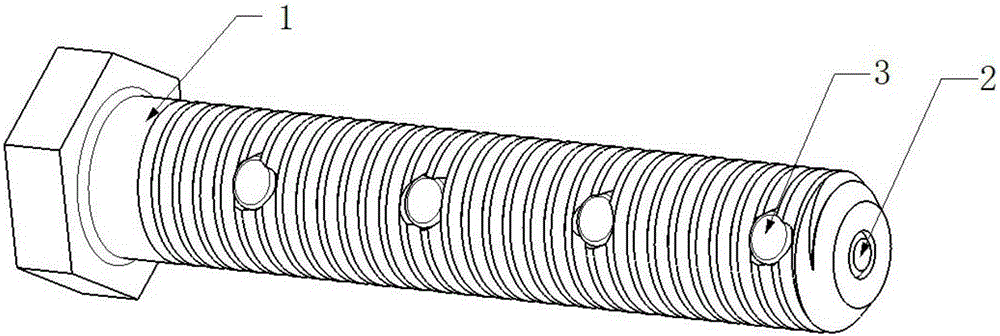
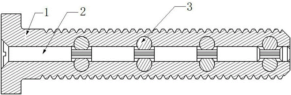
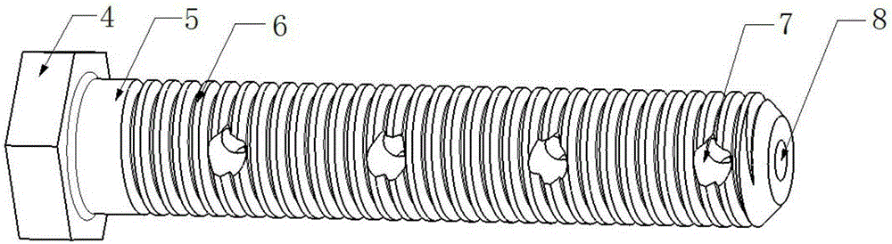
[0024] See Figure 1 to Figure 3 , the present invention includes an external screw 1 and an internal adjusting pin 2, and the center of the screw 1 is provided with an axially penetrating adjusting pin hole 8, and the adjusting pin 2 is located in the adjusting pin hole 8. In this embodiment, the screw 1 includes a head 4 and a stem 5 , and an external thread 6 is provided on the outer wall of the stem 5 .

[0025] See Figure 4 and Figure 5 It can be seen that the adjustment pin 2 includes an adjustment rod 11 with an adjustment end at one end and a tailpiece 12 at the other end, and a plurality of adjustment tooth columns 13 are formed at intervals on the rod body of the adjustment rod 11 . The outer end of the adjusting pin hole 8 is flared to form a groove for accommodating the adjusting ...


PUM


Abstract

The invention relates to a multi-interlayer detachable pin locking thread assembly for a blind hole. The multi-interlayer detachable pin locking thread assembly for the blind hole comprises a screw located outside and an adjustment pin located inside, wherein an axial throughout adjustment pin hole is formed in the center of the screw, and the adjustment pin is located in the adjustment pin hole; the adjustment pin comprises an adjustment rod, an adjustment end socket is arranged at one end of the adjustment rod, and a stop tail is arranged at the other end of the adjustment rod; a plurality of adjustment tooth posts are arranged on a rod body of the adjustment rod at intervals; a groove for containing the adjustment end socket of the adjustment pin is formed in the outer end of the adjustment pin hole in a flaring mode, and the stop tail blocks the other end of the adjustment pin hole; a plurality of groups of stop pin holes are formed inside the screw in the axial direction, the number of the groups is equal to the number of the adjustment tooth posts, and the outer ends of the stop pin holes are communicated with the outside; stop pins are arranged in the multiple groups of stop pin holes; each stop pin comprises a pin rod, adjustment teeth are arranged on the outer wall of each pin rod and connected with the corresponding adjustment tooth post in an engaged mode, and the stop pins stretch out and draw back in the respective stop pin holes when the adjustment pin rotates. The invention further relates to a locking method.

Description

technical field [0001] The invention belongs to the technical field of connectors of threaded components, and in particular relates to a detachable pin-locked threaded component for multi-layered blind holes, and also relates to a locking method using the above-mentioned threaded component. Background technique [0002] In the design of aerospace vehicle parts, a large number of fasteners are usually used as the connection between components, and high-performance fasteners are very expensive. Aerospace vehicles are vibrating all the time during flight, and the vibration will lead to loosening. Therefore, parts are required to have a locking function to effectively control the safety hazards caused by loose parts, which greatly improves the safety requirements of parts. . At present, the locking of blind holes is mainly to use rubber to protrude from the thread of the bolt to produce self-locking, which cannot meet the requirements for high-temperature fields; rubber materia...

Claims


Application Information

Patent Timeline
IPC IPC(8): F16B39/04F16B23/00
Inventor 陈立王鹏蒲国新陈成王洪军王宝秋李紫君
Owner TIANJIN CHENGLI AVIATION TECH CO LTD
Why Eureka
Try Eureka