
Quick connector of iron wire

A wire, fast technology, applied in the direction of transmission elements or pulley ropes or cables, textile cables, belts/chains/gears, etc., can solve problems such as only reach, trouble, disengagement, etc.

Inactive Publication Date: 2016-03-23
无锡市环球电器装备有限公司
View PDF9 Cites 0 Cited by
  • Summary
  • Abstract
  • Description
  • Claims
  • Application Information

AI Technical Summary

Problems solved by technology

In the prior art, a section of casing is used for connection between two steel pipes. Since the outer diameter of the casing is slightly larger than the steel pipe, a step surface is formed due to the unevenness inside the pipe. Due to the existence of the step surface, the iron wire joint is uneven The regular shape is easy to hang on the steps inside the pipe so that the joints can be disengaged, so that the worn cables cannot advance and retreat; at the same time, the existing iron wire joints can withstand a limited tensile force after simple connection, which can only reach 880N, even after the joints are covered with insulating tape. It can only reach 1200N, because the heat pipe in the whole skin system is very long and there are many expansion bends, so when the length of the cable behind the wire pulls is slightly longer or after several pipeline turns, the pulling force is not enough to pull the cable behind, often It will be disengaged at the joint; the current solution is to twist the iron wire into a twisted shape to increase the tensile force that can be tolerated, but this method is relatively troublesome and greatly reduces work efficiency

Method used


Image

  • Quick connector of iron wire
  • Quick connector of iron wire

Examples


Embodiment Construction

[0014] The specific implementation manner of the present invention will be further described in detail below with reference to the drawings and examples. The following examples are used to illustrate the present invention, but are not intended to limit the scope of the present invention.

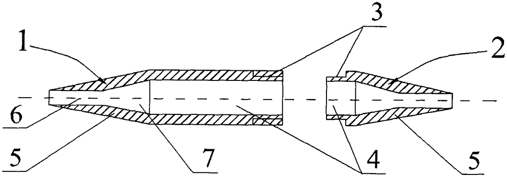
[0015] An iron wire quick connector 10, which is divided into two parts, a long connector 1 and a short connector 2, the long connector 1 and the short connector 2 both include a cylindrical cavity 4 and a conical cavity 5, the long connector 1 and the short connector 2. The two cylindrical cavities 4 are connected by the threaded connection part 3 so that the two cylindrical cavities 4 are docked to form a shuttle-shaped hollow inner cavity. The diameter of the hollow inner cavity is 3.0 to 3.5 times the diameter of the iron wire, preferably about 3.1 times;

[0016] The inner cavity of the tapered cavity 5 is funnel-shaped, and is divided into a funnel neck cavity 6 and a funnel mouth cavi...


PUM


Abstract

The invention relates to a quick connector of an iron wire. The quick connector is divided into a long connector and a short connector which form a shuttle shaped hollow inner cavity through thread connecting parts, wherein the hollow inner cavity is divided into a middle cylindrical cavity body, and tapered cavity bodies which are arranged at two sides and communicate with the cylindrical cavity body; the diameter of the hollow inner cavity is 3.0 to 3.5 times that of the iron wire; the diameter of a funnel-shaped neck chamber in each tapered cavity body is 1.1 to 1.5 times that of the iron wire. The connector is applied whena cable passes through a steel tube; after iron wire heads are bent and mutually buckled, the inner wall of the cylindrical inner cavity of the connector clings to the iron wire during the pulling process, and a large extrusion force can be accordingly generated to effectively prevent the iron wire connector from disconnecting. Compared with the prior art, the quick connector of the iron wire has the advantages that the structure is unique and reasonable, and the iron wire can be easily and quickly connected, so that the working efficiency can be improved; in addition, the borne pull force is up to 2500N, thus the demand during the penetrating of the cable can be met, and the cable is not easy to disconnect.

Description

technical field [0001] The invention relates to the technical field of electric cables, in particular to a lead iron wire joint used for passing cables in steel pipes, which is easy to operate, has a large bearing capacity and is not easy to disengage. Background technique [0002] At present, the skin effect heat tracing technology, as a new metal pipeline heating method that has emerged in recent years, is a new technology and new process for heating and heat preservation of large-scale petrochemical and other enterprises' heat transmission pipelines. It has high efficiency and is suitable for all long, medium and The heat tracing and heating of the short-distance metal infusion pipeline has the advantages of safety, reliability, and convenient installation and maintenance, so it is widely used in the pipeline transportation of various liquid substances with different properties. [0003] In the actual application of this technology, it is necessary to pass the cable throu...

Claims


Application Information

Patent Timeline
IPC IPC(8): F16G11/10
Inventor 蔡煜杰
Owner 无锡市环球电器装备有限公司
Learn More