Tunnel lamp with adjustable illumination angle

A lighting angle and adjustable technology, applied in the field of tunnel lights, can solve the problems of unsatisfactory lighting effect, fragile and difficult to transport, unfavorable air circulation, etc. area effect

Inactive Publication Date: 2016-03-23
CHONGQING BEACON OPTOELECTRONICS TECH
View PDF0 Cites 5 Cited by
  • Summary
  • Abstract
  • Description
  • Claims
  • Application Information

AI Technical Summary

Problems solved by technology

[0002] Tunnel light is a special lamp for tunnel lighting to solve the "black hole effect" or "white hole effect" caused by the sudden change in brightness when the vehicle enters or exits the tunnel. The light source of the tunnel light generally uses sodium lamp, gold Halogen lamps sometimes use electrodeless lamps, but these light sources use high-voltage, high-current and glass covers, which are large in size, heavy in weight, fragile and difficult to transport, high in energy consumption, serious in environmental pollution, short in life, and unsatisfactory in lighting effects. LED lights are more common. LED lights have the advantages of less energy consumption, strong applicability, short response time, no pollution to the environment, and multi-color light emission. However, LED lights also have many shortcomings. If they need to achieve sufficient heat dissipation , you need to use aluminum alloy materials with high thermal conductivity to process and cast, which is expensive and costly. The radiator is usually large in size, which makes the LED lamp look bulky and difficult to meet the requirements of the lamp design. The radiator is often combined with other components. Too close is not conducive to air circulation and affects the heat dissipation effect. In recent years, LED lights have developed rapidly, and one of the core technologies of LED lights is heat dissipation technology, so radiators play a vital role in the performance of LED lights

Method used


Image

  • Tunnel lamp with adjustable illumination angle
  • Tunnel lamp with adjustable illumination angle
  • Tunnel lamp with adjustable illumination angle

Examples


Embodiment Construction

[0023] The present invention will be further described below in conjunction with the embodiments and accompanying drawings.

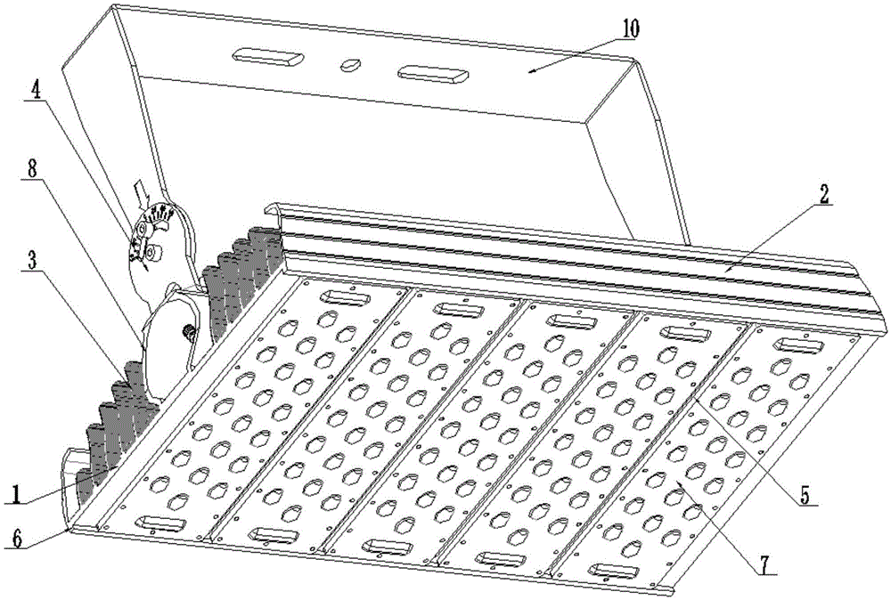
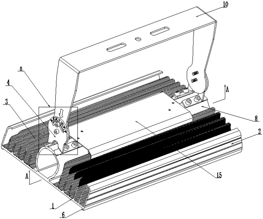
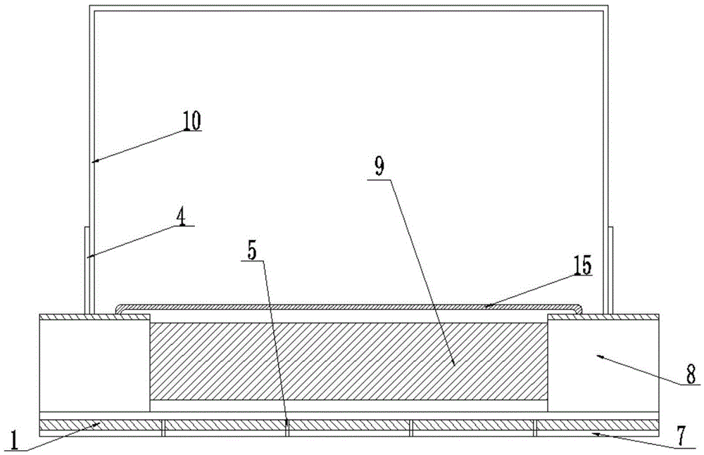
[0024] like Figure 1-5 As shown, a tunnel lamp with an adjustable lighting angle includes a base plate 1 on which a light-emitting component 7 is arranged.

[0025] Two protective baffles 2 are arranged along the length direction on the same side of the lamp socket bottom plate 1, and the two protective baffles 2 are respectively connected to the edge of the lamp socket bottom plate 1, and the two protective baffles The bottom plate 1 of the lamp holder between 2 is provided with a power supply mounting seat 8 and comb-shaped heat dissipation fins 3 along the length direction, and the power supply mounting seat 8 and heat dissipation fins 3 and the protective baffle 2 are located on the On the same side of the base plate 1 of the lamp holder, two supports 4 are arranged on the power supply mounting base 8, and the two supports 4 are located at both en...


PUM


Abstract

Disclosed is a tunnel lamp with an adjustable illumination angle. The tunnel lamp with the adjustable illumination angle comprises a lamp holder base plate. A light emitting assembly is arranged on the lamp holder base plate. Two protecting baffles are arranged on the same side of the lamp holder base plate in the length direction and connected with the edges of the lamp holder base plate respectively. A power source installation base and cooling fins are arranged on the portion, between the two protecting baffles, of the lamp holder base plate in the length direction, and the power source installation base, the cooling fins and the protecting baffles are located on the same side of the lamp holder base plate. Two supporting bases are arranged on the power source installation base, and the same lamp holder support is arranged between the two supporting bases in a connected mode. A power source installation groove is formed in the power source installation base, and a power source is arranged in the power source installation groove and electrically connected with the light emitting assembly. According to the invention, due to the facts that the cooling fins are in a comb tooth shape, and the surface of each cooling fin is zigzag, the heat dissipation area is greatly increased. Due to the fact that the protecting baffles are arranged on the two sides of the cooling fins, the phenomenon that an installation worker is cut by the cooling fins when the tunnel lamp is installed can be effectively avoided. The whole tunnel lamp is compact in structure, wide in application range, good in heat dissipation performance and attractive in appearance.

Description

technical field [0001] The invention relates to a lighting device, in particular to a tunnel lamp with adjustable lighting angle. Background technique [0002] Tunnel light is a special lamp for tunnel lighting to solve the "black hole effect" or "white hole effect" caused by the sudden change in brightness when the vehicle enters or exits the tunnel. The light source of the tunnel light generally uses sodium lamp, gold Halogen lamps sometimes use electrodeless lamps, but these light sources use high-voltage, high-current and glass covers, which are large in size, heavy in weight, fragile and difficult to transport, high in energy consumption, serious in environmental pollution, short in life, and unsatisfactory in lighting effects. LED lights are more common. LED lights have the advantages of less energy consumption, strong applicability, short response time, no pollution to the environment, and multi-color light emission. However, LED lights also have many shortcomings. If...

Claims


Application Information

Patent Timeline
Patent Type & Authority Applications(China)
IPC IPC(8): F21S8/00F21V29/76F21V21/108F21V17/02F21V17/12F21W131/101F21Y115/10
CPCF21S8/00F21V17/02F21V17/12F21V21/108F21W2131/101
Inventor 邵群
Owner CHONGQING BEACON OPTOELECTRONICS TECH
Why Eureka
Try Eureka