Humidity-sensor-chip mass production testing device and method

A technology of humidity sensor and test method, which is applied in the direction of measuring devices, instruments, scientific instruments, etc., can solve the problems of long time consumption, long test time, complicated test device, etc., and achieve accurate measurement results, short test time and high test accuracy Effect

Active Publication Date: 2016-03-23
SHANGHAI SHENXILING MICROELECTRONICS TECH CO LTD
View PDF9 Cites 4 Cited by
  • Summary
  • Abstract
  • Description
  • Claims
  • Application Information

AI Technical Summary

Problems solved by technology

[0004] The current test method, in order to ensure the accuracy, needs to be measured under multiple humidity conditions. At the same time, in order to correct the temperature coefficient, it also needs to be measured under multiple temperature conditions. The test time is long. For example, the Chinese application number is 201510114499.3, and the name is a humidity. The patent application for the sensor response time measurement device and measurement method needs to measure two sets of data under two different humidity conditions. In addition, the test device is complicated and the test time is long, which is not convenient for mass production
Another example is that the application number is 03800112.8, and the name is a patent application for a humidity sensor calibration method and device and a sensing device with a calibrated humidity sensor. Although it does not need to be tested under multiple temperature conditions, it is necessary to test two pressure conditions Group data, the same test device is complex and time-consuming
Another example is that the Chinese application number is 201180030822.9, and the name is a patent application for a humidity sensor test method and its sensor module. Although it is tested at one humidity point and one temperature point, it is impossible to test accurate relative humidity data. Qualitatively judge whether the humidity sensor is working normally

Method used


Image

  • Humidity-sensor-chip mass production testing device and method
  • Humidity-sensor-chip mass production testing device and method
  • Humidity-sensor-chip mass production testing device and method

Examples


Embodiment Construction

[0047] The present invention will be described in detail below in conjunction with specific embodiments. The following examples will help those skilled in the art to further understand the present invention, but do not limit the present invention in any form. It should be noted that those skilled in the art can make several modifications and improvements without departing from the concept of the present invention. These all belong to the protection scope of the present invention.

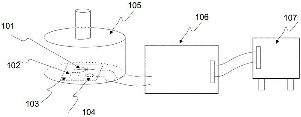
[0048] In this embodiment, the test device for mass production of humidity sensor chips provided by the present invention includes a measurement chamber, a temperature sensor, a calibrated humidity sensor, a LoadBoard test daughter board, a LoadBoard test motherboard and a test machine;

[0049] Wherein, the temperature sensor, the calibrated humidity sensor and the LoadBoard test sub-board are arranged in the measurement chamber; the calibrated humidity sensor and the temperature sensor are arrang...


PUM


Abstract

The invention provides a humidity-sensor-chip mass production testing device and method. The testing device comprises a testing cavity, a temperature sensor, a calibrated humidity sensor, a Load Board testing secondary board, a Load Board testing primary board and a testing machine. The temperature sensor, the calibrated humidity sensor and the Load Board testing secondary board are arranged in the testing cavity. The calibrated humidity sensor and the temperature sensor are arranged on the Load Board testing secondary board. The Load Board testing primary board is electrically connected with the Load Board testing secondary board. The testing machine is electrically connected with the Load Board testing primary board. According to the humidity-sensor-chip mass production testing device and method, the constant-temperature condition and the constant-humidity condition are avoided, complex auxiliary devices are avoided, and the waiting time required for achieving the constant temperature and the constant humidity is also saved.

Description

technical field [0001] The invention relates to a humidity sensor chip, in particular to a test device and a test method for mass production of the humidity sensor chip. Background technique [0002] As one of the basic physical quantities, humidity needs to be collected in production activities in the fields of industry, agriculture, and medical care, as well as in people's lives. As an important means of humidity collection, humidity sensor chips have broad applications in fields including personal computers, communications, and medical health. application prospects. Especially with the rise of the Internet of Things, wearable devices, and smart homes, there is an urgent need for a fast, economical, and mass-produced measurement method. This test method is based on the humidity sensitive capacitance C X Has a quantitative functional relationship with humidity, where the humidity sensitive capacitance C X and resistor R 1 A resonant circuit is formed to generate a reson...

Claims


Application Information

Patent Timeline
IPC IPC(8): G01N27/22
CPCG01N27/223
Inventor 王玉
Owner SHANGHAI SHENXILING MICROELECTRONICS TECH CO LTD
Why Eureka
Try Eureka