
Engine rotating speed measurement circuit and method

An engine speed and measurement circuit technology, which is applied to devices using electrical/magnetic methods, etc., can solve the problems of singular waveforms, inability to meet the high reliability and high precision measurement requirements of the speed detection system, and complex signals, and achieve the realization of The effect of rotating speed, increasing accuracy and reliability, and stable and reliable system operation

Active Publication Date: 2016-03-23
XIAN AVIATION COMPUTING TECH RES INST OF AVIATION IND CORP OF CHINA
View PDF5 Cites 36 Cited by
  • Summary
  • Abstract
  • Description
  • Claims
  • Application Information

AI Technical Summary

Problems solved by technology

[0003] In fact, the signal output by the engine speed sensor is relatively complex, and even has a strange waveform
Such a waveform cannot meet the high-reliability and high-precision measurement requirements of the speed detection system. Therefore, the output signal of the speed sensor must be pre-conditioned to convert it into a square wave signal with the same frequency as the original signal and a voltage range that meets certain requirements.

Method used


Image

  • Engine rotating speed measurement circuit and method
  • Engine rotating speed measurement circuit and method
  • Engine rotating speed measurement circuit and method

Examples


Embodiment Construction

[0033] Below in conjunction with accompanying drawing and embodiment, the present invention will be further described, and the rotational speed of a certain type of engine is collected, and the frequency range required to be collected is (89Hz~10000Hz):

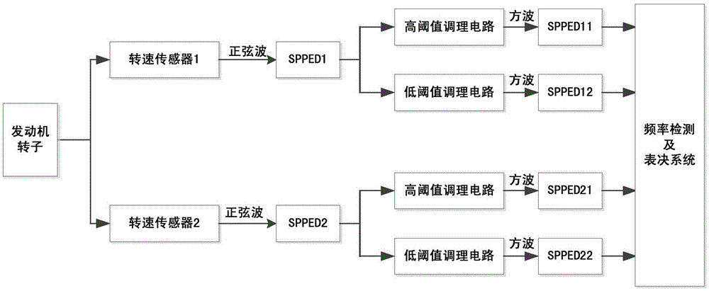
[0034] The functional schematic diagram of the measurement system is shown in figure 1 As shown, the system mainly includes two speed sensors, four speed sensor signal conditioning circuits (including high threshold conditioning circuits and low threshold conditioning circuits), frequency measurement and voting methods.

[0035] The functional schematic diagram of the speed sensor signal conditioning circuit is as follows: figure 2 As shown, the hardware schematic diagram is shown in image 3 As shown, the circuit mainly includes a band-pass filter circuit, a limiter circuit, a differential amplifier circuit and a hysteresis comparison circuit, where the capacitance values ​​of C1_1 and C2_2 are C1, and the resistance value...


PUM


Abstract

The invention provides an engine rotating speed measurement circuit and a method. Two independent rotating speed sensors simultaneously collect engine rotating speeds. Each rotating speed sensor output signal is regulated through two kinds of non-similar redundancy conditioning circuits of high and low thresholds and then square wave signals are output and are collected by a frequency measurement apparatus. Through voting, a final engine rotating speed is acquired. The circuit and the method possess characteristics that precision is high; an anti-interference capability is high and reliability is high and can be used for an aviation engine rotating speed detection system with a wide flight envelope and a complex usage environment.

Description

Technical field: [0001] The invention belongs to the field of rotating machine speed monitoring, and in particular relates to a rotating machine speed measuring circuit and method. Background technique: [0002] Speed ​​is an extremely important parameter for evaluating engine performance, monitoring the test run process, and designing data systems, and it is also a commonly used controlled quantity for engines. In the engine control system, the measurement of the engine speed is often involved, and the control system has high requirements for the accuracy of the speed measurement. The accurate and real-time measurement of the speed is of great significance to ensure the normal operation and safety of the engine. [0003] In fact, the signal output by the engine speed sensor is more complicated, and even a strange waveform appears. Such a waveform cannot meet the high-reliability and high-precision measurement requirements of the speed detection system. Therefore, the outpu...

Claims


Application Information

Patent Timeline
Patent Type & Authority Applications(China)
IPC IPC(8): G01P3/44
CPCG01P3/44
Inventor 王浩刘晓杨恒辉赵小勇毛宁徐杰
Owner XIAN AVIATION COMPUTING TECH RES INST OF AVIATION IND CORP OF CHINA
Learn More