Transverse multi-focus generation device and method

A production method and production device technology, applied in optical components, optics, instruments, etc., can solve the problems of non-adjustable focus position and lack of flexibility.

Inactive Publication Date: 2016-03-23
LUDONG UNIVERSITY
View PDF2 Cites 20 Cited by
  • Summary
  • Abstract
  • Description
  • Claims
  • Application Information

AI Technical Summary

Problems solved by technology

In 2014, it was reported that the polarization direction control of multiple focal points can be achieved by phase modulation of azimuthally polarized beams...

Method used


Image

  • Transverse multi-focus generation device and method
  • Transverse multi-focus generation device and method
  • Transverse multi-focus generation device and method

Examples


Embodiment 1

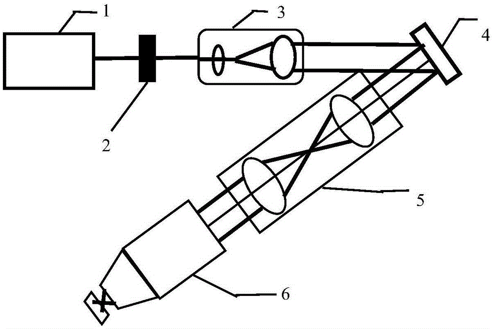
[0043] Such as figure 1 As shown, a horizontal multi-focus generating device includes:

[0044] Laser 1, for emitting a laser beam with arbitrary polarization;

[0045] Polarizer 2, for converting the laser beam of arbitrary polarization into a linearly polarized laser beam;

[0046] Beam expansion and collimation system 3, used to expand and collimate the linearly polarized laser beam;

[0047] The spatial light modulator 4 is used to phase-modulate the collimated and expanded linearly polarized laser beam;

[0048] 4F Fourier transform imaging system 5, for imaging the phase-modulated linearly polarized laser beam to the rear aperture position of the objective lens;

[0049] The objective lens 6 is used to focus the phase-modulated laser beam, and multiple transverse focuses will be generated in the focus area, and the phase and transverse position of each focus can be adjusted arbitrarily.

[0050] Such as Figure 2 to Figure 10 As shown, a horizontal multi-focal gener...

Embodiment 2

[0067] Assumption: incident laser wavelength λ=633nm, objective lens numerical aperture N.A.=1, refractive index n in the focal area t = 1.33, the entrance pupil radius R = 3.25 mm, providing a specific example of producing phase and position adjustable lateral 4 focal points.

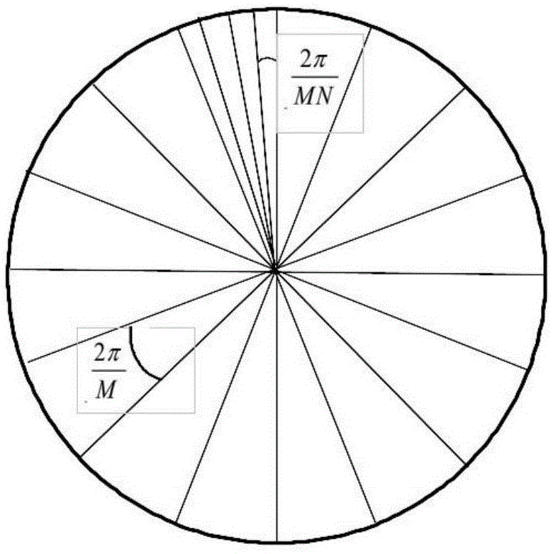
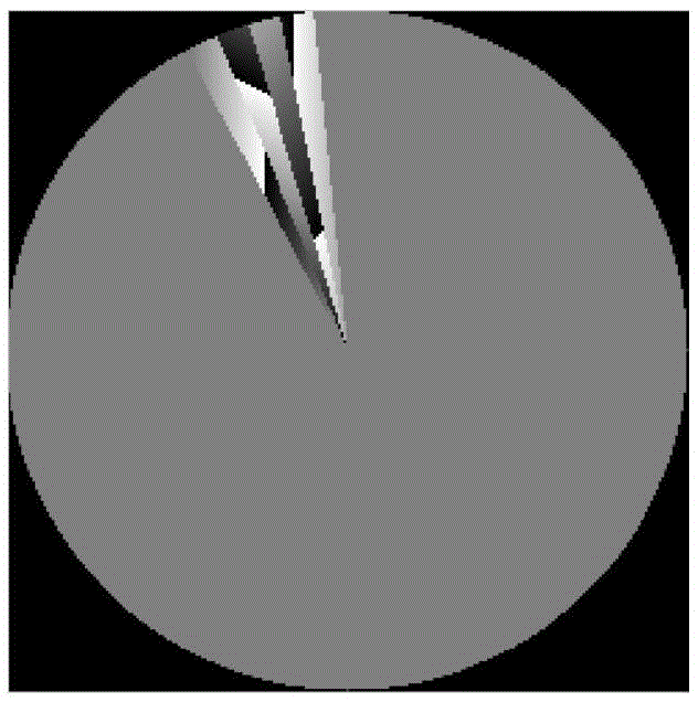
[0068] Figure 5 In order to generate the phase modulation diagram of the four focal points in the horizontal direction; the fan-shaped partition parameters of the phase modulation diagram are: M=75, N=4; the displacements of the four focal points relative to the center are: Δx 1 =-3μm, Δy 1 = 0, Δx 2 = -1 μm, Δy 2 = 1 μm, Δx 3 = 1 μm, Δy 3 = 2μm, Δx 4 =3μm,Δy 4 =0; the additional phase of each focal point is: Δψ 1 =π / 4,Δψ 2 =π / 3,Δψ 3 = π,Δψ 4 = π / 6.

[0069] Figure 6 for the reason Figure 5 The intensity profile of the four lateral foci produced by the phase modulation map.

[0070] Figure 7 for the reason Figure 5 Transverse four-focal phase maps generated from phase modulation m...

Embodiment 3

[0072] Assumption: incident laser wavelength λ=633nm, objective lens numerical aperture N.A.=1, refractive index n in the focal area t = 1.33, entrance pupil radius R = 3.25 mm, providing a specific example of producing phase and position adjustable lateral 6 focal points.

[0073] Figure 8 In order to generate the phase modulation diagram of six focal points in the horizontal direction, the parameters of the fan-shaped partition of the phase modulation diagram are: M=75, N=6. The displacements of the six focal points relative to the center are: Δx 1 =-3.5μm, Δy 1 = 0, Δx 2 =-2.1μm, Δy 2 =-3μm, Δx 3 =-0.7μm, Δy 3 = 0, Δx 4 = 0.7 μm, Δy 4 = 0, Δx 5 =2.1μm,Δy 5 =-3μm, Δx 6 =3μm,Δy 6 =0; the additional phase of each focal point is: Δψ 1 = π / 6, Δψ 2 = π, Δψ 3 = π / 4, Δψ 4 = π / 4, Δψ 5 = π, Δψ 6 = π / 6.

[0074] Figure 9 for the reason Figure 8 Intensity profile of the six transverse foci produced by the phase modulation map.

[0075] Figure 10 for the reaso...


PUM


Abstract

The invention relates to a transverse multi-focus generation device. The device comprises a laser device which is used for generating laser beams of arbitrary polarization; a polaroid which is used for converting the laser beams of arbitrary polarization into laser beams of linear polarization; a beam expansion and collimation system which is used for performing beam expansion and collimation on the laser beams of linear polarization; a spatial light modulator which is used for performing phase modulation on the linear polarization laser beams after beam expansion and collimation; a 4F Fourier transform imaging system which is used for performing imaging of the linear polarization laser beams after phase modulation to an aperture position behind an object lens; and the object lens which is used for focusing of the laser beams after phase modulation and generating transverse multiple focuses in a focus area, wherein the phase and the transverse position of each focus are arbitrarily adjustable. Compared with devices in the prior art, adjustable position and phase of each focus and controllable number of the focuses can be realized simultaneously.

Description

technical field [0001] The invention relates to a horizontal multi-focus generation device and method with adjustable focus position, quantity and phase of each focus. Background technique [0002] The spot produced by laser focusing through a high numerical aperture objective lens has a very wide range of applications in many fields such as high-resolution fluorescence imaging, laser material processing, optical data storage, micro particle manipulation, artificial microstructure material preparation, surface plasmon excitation, etc. Therefore, it has always been a very important research direction to generate various intensity distributions and polarization distributions in the focal area by modulating the amplitude, phase, and polarization of the incident laser light. At present, there are extensive and in-depth research reports on the generation of annular spot, chain spot, pinpoint spot, sub-wavelength spot, spiral spot, two-dimensional array spot and three-dimensional ...

Claims


Application Information

Patent Timeline
IPC IPC(8): G02B27/09G02B27/28
CPCG02B27/0927G02B27/0938G02B27/286
Inventor 陈建农
Owner LUDONG UNIVERSITY
Why Eureka
Try Eureka