Virtual local area network configuration method and system of passive optical network

A technology of passive optical fiber network and virtual local area network, which is applied in the direction of transmission system, digital transmission system, data exchange network, etc. It can solve the problems of weak multiple VLAN modes and unable to solve PONMAC function, etc., and achieve the effect of easy configuration and recovery

Active Publication Date: 2016-03-23
湖州帷幄知识产权运营有限公司
View PDF7 Cites 2 Cited by
  • Summary
  • Abstract
  • Description
  • Claims
  • Application Information

AI Technical Summary

Problems solved by technology

[0005] In view of the shortcomings of the prior art described above, the purpose of the present invention is to provide a virtual local area network configuration method and system for a passive optical fiber network, which is used to solve the problem that PON equipment in the prior art can only realize

Method used


Image

  • Virtual local area network configuration method and system of passive optical network
  • Virtual local area network configuration method and system of passive optical network
  • Virtual local area network configuration method and system of passive optical network

Examples


Example Embodiment

[0039] Example one

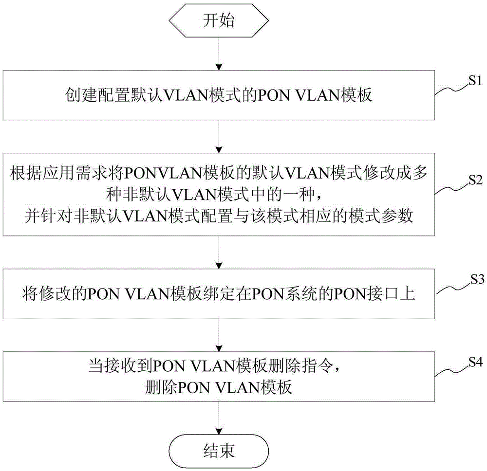
[0040] This embodiment provides a virtual local area network configuration method for a passive optical fiber network, which is applied to the optical line terminal (OLT) side of a passive optical network (PON) system, and the optical line terminal (OLT) is provided with a passive optical fiber network interface , The virtual local area network configuration method of the passive optical fiber network includes the following steps:

[0041] Creating a passive optical fiber network virtual local area network template configured with a default virtual local area network mode; the passive optical network virtual local area network template can be configured with multiple non-default virtual local area network modes;

[0042] Modify the default virtual local area network mode of the passive optical fiber network virtual local area network template to one of multiple non-default virtual local area network modes according to application requirements, and configure the c...

Example Embodiment

[0151] Example two

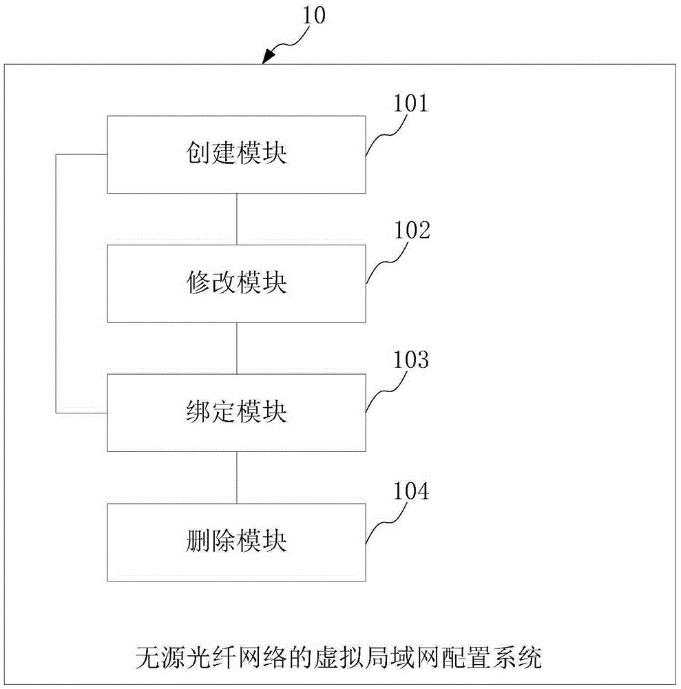
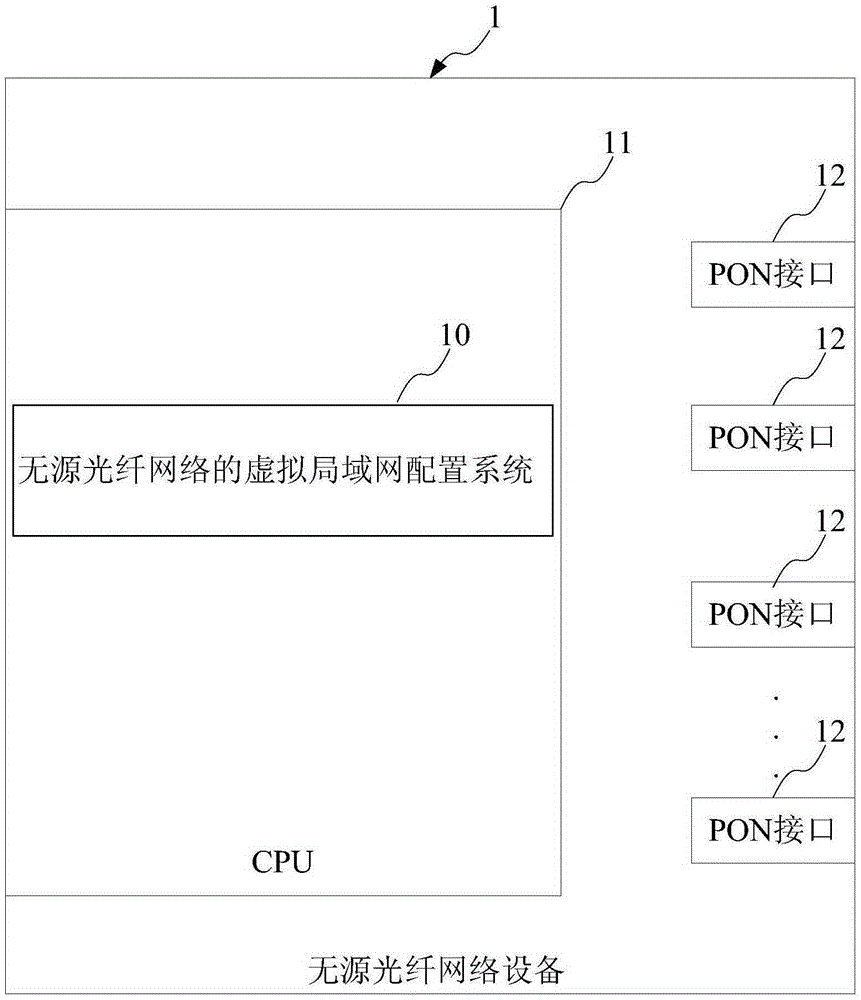
[0152] This embodiment provides a virtual local area network configuration system for a passive optical fiber network, which is applied to the optical line terminal side in a passive optical fiber network system. The optical line terminal is provided with a passive optical fiber network interface. The LAN configuration system includes:

[0153] The creation module is used to create a passive optical fiber network virtual local area network template configured with a default virtual local area network mode; the passive optical network virtual local area network template can be configured with multiple non-default virtual local area network modes;

[0154] The modification module, connected to the creation module, is used to modify the default virtual local area network mode of the passive optical fiber network virtual local area network template to one of multiple non-default virtual local area network modes according to application requirements, and configure for...


PUM


Abstract

The invention provides a virtual local area network configuration method of a passive optical network. The method includes: a passive optical network virtual local area network template in a default virtual local area network mode is created and configured; the passive optical network virtual local area network template can be provided with a plurality of non-default virtual local area network modes; according to the application requirement, the default virtual local area network mode of the passive optical network virtual local area network template is modified to one of a plurality of non-default virtual local area network modes, and mode parameters corresponding to the non-default virtual local area network mode are configured according to the mode; and the modified passive optical network virtual local area network template is bound to a passive optical network interface. According to the method, the problem that various VLAN modes cannot be realized at the PON interface due to weak PON MAC function is solved, and more VLAN modes such as VLAN transparent mode, VLAN marked/unmarked mode, VLAN relay mode, 1:1VLAN conversion mode, and N:1VLAN aggregation mode are realized.

Description

technical field [0001] The invention belongs to the technical field of gigabit passive optical networks, and relates to a configuration method and system, in particular to a virtual local area network configuration method and system of a passive optical fiber network. Background technique [0002] According to the technical requirements of China Telecom's PON equipment, the OLT should support VLAN transparent transmission, VLAN marking / de-marking, VLANTrunk, VLAN conversion, and N:1VLAN aggregation functions. For the VLANTrunk function, each PON port should support 4K VLANs, and the range of VLANIDs is 1-4094. For the VLAN translation function, each PON port should support no less than 512 VLANTranslation entries. For the N:1 VLAN aggregation function, the N of each PON port should not be less than 64. In addition, the OLT should also support the hybrid use of VLAN translation and N:1 VLAN aggregation. [0003] However, the existing technology can only realize four VLAN m...

Claims


Application Information

Patent Timeline
IPC IPC(8): H04L12/24H04Q11/00
CPCH04L12/4633H04L41/08H04L41/0823H04Q11/0062
Inventor 李俊奎
Owner 湖州帷幄知识产权运营有限公司
Why Eureka
Try Eureka