Continuous phase change heat sink thermal control unit

A technology of thermal control and phase change heat, which is applied in cooling/ventilation/heating transformation, modification using liquid cooling, etc. It can solve the problems of difficult technical implementation, high cost of modified phase change materials, poor technical economy, etc., and achieve high efficiency. Effect of heat transfer and energy storage, simple technical solution, and quick start performance

Active Publication Date: 2016-03-23
10TH RES INST OF CETC
View PDF3 Cites 2 Cited by
  • Summary
  • Abstract
  • Description
  • Claims
  • Application Information

AI Technical Summary

Problems solved by technology

[0003] The purpose of the present invention is to aim at the deficiencies of the existing technology, to provide a continuous phase change heat sink heat control unit with simple principle, low cost and phase change materials, so as to overcome the high cost of traditional modified phase change materials and technical problems. Difficult implementation and poor technical economy

Method used


Image

  • Continuous phase change heat sink thermal control unit

Examples


Embodiment Construction

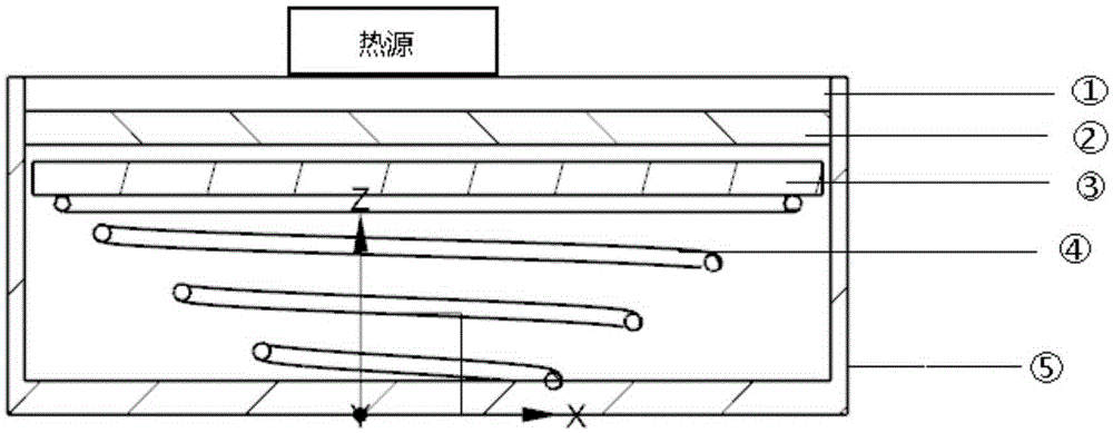
[0012] refer to figure 1 . In the embodiments described below, the thermal control unit of the continuous phase change heat sink includes the phase change material 2 packaged in the closed cavity of the packaging case 5 . A conical spring 4 supporting the pre-tightening pressure plate 3 is provided at the bottom end of the closed cavity of the packaging shell 5, and the phase change material 2 is arranged between the thermal diffusion plate 1 and the pre-tightening pressure plate 3, and the spring pre-tensioning force of the conical spring 4 is Press the phase change material 2 close to the thermal diffusion plate 1. During the phase change process, when the heat source generates heat, the temperature of the heat source and the thermal diffusion plate 1 rises, and the heat source is transferred to the phase change material 2 through the thermal diffusion plate 1 to undergo a phase change. , the phase change material 2 near the inner wall surface of the thermal diffusion plate...


PUM


Abstract

The invention discloses a continuous phase change heat sink thermal control unit and aims to provide a phase change material thermal control unit simple in principle and low in realization cost. The thermal control unit is realized by the following technical scheme: a conical spring for supporting a pre-tightening pressure plate is arranged at the bottom end of a sealed cavity of a packaging shell; a phase change material is arranged between a heat diffusion plate and the pre-tightening pressure plate; the phase change material is closely pressed on the heat diffusion plate through pre-tightening force of the conical spring; in a phase change process, a heat source is transmitted to the phase change material for phase change through the heat diffusion plate, so that the phase change material at an interface of the phase change material and the heat diffusion plate is softened; the conical spring transmits the pre-tightening force of the spring to the interface of the phase change material and the heat diffusion plate through the pre-tightening pressure plate, so that the softened and molten phase change material is pushed and extruded out of the interface of the heat diffusion plate and the phase change material, and the phase change material is discharged to one side of the conical spring from a gap between the pre-tightening pressure plate and the packaging shell; and the phase change material is thinned under the action of spring force of the conical spring, and continuous melting phase change of continuous thinning is generated, so that efficient heat transmission and energy storage are realized.

Description

technical field [0001] The invention relates to a phase change heat sink which utilizes the principle of phase change heat transfer to transfer heat to electronic equipment. Background technique [0002] With the high frequency and high speed of electronic devices and the rapid development of integrated circuit technology and technological progress, the total power density of electronic components has increased significantly while the physical size has become smaller and smaller, and the heat flux has also increased. Therefore, high temperature The temperature environment will inevitably affect the performance of electronic components, which requires more efficient thermal control. Therefore, effectively solving the heat dissipation problem of electronic components has become a key technology in the manufacture of electronic components and electronic equipment. With the rapid development of microelectronics technology, the miniaturization of electronic devices has become th...

Claims


Application Information

Patent Timeline
Patent Type & Authority Applications(China)
IPC IPC(8): H05K7/20
CPCH05K7/2029
Inventor 胡家渝
Owner 10TH RES INST OF CETC
Why Eureka
Try Eureka