Cleaning machine for rack parts of automobile steering devices

A technology for automobile steering gear and washing machine, which is applied in the directions of dryers, chemical instruments and methods, cleaning methods and utensils, etc. Cleaning mode, etc.

Active Publication Date: 2016-03-30
荆州恒隆汽车零部件制造有限公司
View PDF5 Cites 34 Cited by
  • Summary
  • Abstract
  • Description
  • Claims
  • Application Information

AI Technical Summary

Problems solved by technology

There are many human factors in the former, low work efficiency, high labor intensity of workers, the consistency of cleaning effect cannot be guaranteed, and the process capability is poor, which cannot meet the requirements of industrial production.
Since the latter uses the same liquid tank, it is difficult to achieve a two-level or multi-level cleaning mode. At the same time, because the rack parts are slender rods with slender deep holes inside and irregular teeth on the outside, they cannot be fixed In the rotating liquid tank, the impurities in the slender and deep holes cannot be effectively cleaned out
It is difficult to improve the cleaning effect at a high level
At the same time, even if the ultrasonic vibrating plate is used for cleaning, only the surface problems of the parts can be solved in one liquid tank, and it is difficult to solve the removal of impurities in the elongated holes.

Method used


Image

  • Cleaning machine for rack parts of automobile steering devices

Examples


Embodiment Construction

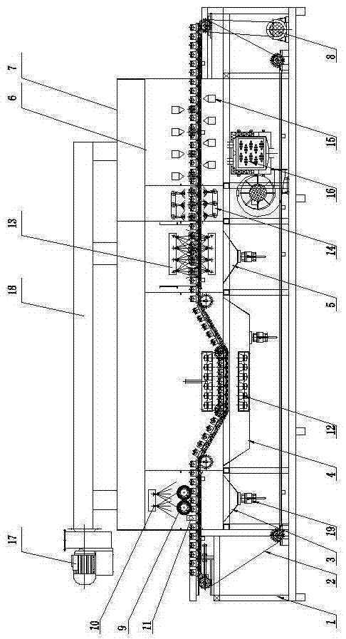
[0016] The automotive steering gear rack parts cleaning machine is composed of a frame 1, a conveyor chain 2, a spray scrub tank 3, an ultrasonic cleaning tank 4, a high-pressure spray cleaning tank 5, a drying room 6 and an electrical control box. A cleaning chamber 7 is installed across the frame 1; a conveyor chain 2 is installed on the top of the frame 1 through a drive shaft and a motor 8. One end of the rack 1 is provided with an electrical control box (not shown in the figure). The conveyor chain 2 one end in the cleaning chamber 7 is equipped with a spray scrub tank 3 by the frame 1 below, and the spray scrub tank 3 top is equipped with a rolling brush 9 by the frame 1. Spray cleaning head 10 is housed by frame 1 above the rolling brush 9 . One side of rolling brush 9 ends is equipped with high-pressure nozzle 11 by frame 1. The high-pressure nozzle 11 is used for cleaning the elongated deep holes of the rack parts.

[0017] An ultrasonic cleaning tank 4 is installe...


PUM


Abstract

The invention relates to a cleaning machine for rack parts of automobile steering devices and belongs to the field of cleaning equipment for racks of the automobile steering devices. The cleaning machine is composed of a machine frame, a conveying chain, a spraying and scrubbing tank, an ultrasonic cleaning tank, a high-pressure spraying and cleaning tank, a drying room and an electric appliance control box. The spraying and scrubbing tank is arranged below one end of the conveying chain in a cleaning room. The ultrasonic cleaning tank is arranged at the portion, on one side of the spraying and scrubbing tank, of the machine frame. An ultrasonic vibration plate is arranged on the portion, corresponding to the conveying chain, of the ultrasonic cleaning tank and connected with an ultrasonic generator. The cleaning machine is small in occupied area and convenient to operate. Working efficiency is improved and is high, the cleanliness and cleanliness quality of rack workpieces are guaranteed, and the problems that a manual one-by-one scrubbing manner is adopted for existing steering device rack products, so that working efficiency is low, it is difficult to keep the same cleanliness quality, the labor intensity of workers is larger, and the industrial production requirements cannot be met are avoided. The cleaning machine is especially suitable for cleaning and use of rack products of the steering devices.

Description

technical field [0001] The invention relates to a cleaning machine for automobile steering gear rack parts, which belongs to the field of cleaning equipment for automobile steering gear racks. Background technique [0002] The rack parts of the automobile steering gear, whether in hydraulic power steering gear, mechanical steering gear or electronic power steering gear, are indispensable and one of the most important parts. Its main function is to convert the rotational torque into a vertical push-pull torque. Its structural characteristics are that the surface of the slender cylinder has a tooth shape, and the inside has a slender hole that exceeds half the total length. The surface part has quenching treatment to increase the hardness. Its material is generally For high carbon steel or alloy steel. Since the rack part is in the sealing part of the oil cylinder in the working condition of the steering gear, which is equivalent to the piston rod, it has extremely high requi...

Claims


Application Information

Patent Timeline
Patent Type & Authority Applications(China)
IPC IPC(8): B08B1/02B08B3/02B08B3/12B08B13/00F26B21/00
CPCB08B1/02B08B3/022B08B3/123B08B13/00F26B21/001
Inventor 邓勇强文卫平冯强王涛柏姬伟
Owner 荆州恒隆汽车零部件制造有限公司
Why Eureka
Try Eureka