Locking device for machining mechanical parts

A technology for locking devices and mechanical parts, applied in metal processing mechanical parts, positioning devices, metal processing equipment, etc., can solve the problems of limiting the working range of the locking device, inability to process mechanical parts, poor operability, etc., to simplify circuit design, Improve the quality of processing and the effect of convenient and quick maintenance

Inactive Publication Date: 2016-03-30
SHENGZHOU YIHAI MOTOR PARTS FACTORY
View PDF0 Cites 6 Cited by
  • Summary
  • Abstract
  • Description
  • Claims
  • Application Information

AI Technical Summary

Problems solved by technology

[0003] In the prior art, the locking device is directly fixed on the machine tool, and the locking device cannot be moved, which limits the working range of the locking device, and can only clamp mechanical parts of the same size, and cannot process mechanical parts of other sizes. Poor practicability, poor operability

Method used


Image

  • Locking device for machining mechanical parts
  • Locking device for machining mechanical parts
  • Locking device for machining mechanical parts

Examples


Embodiment Construction

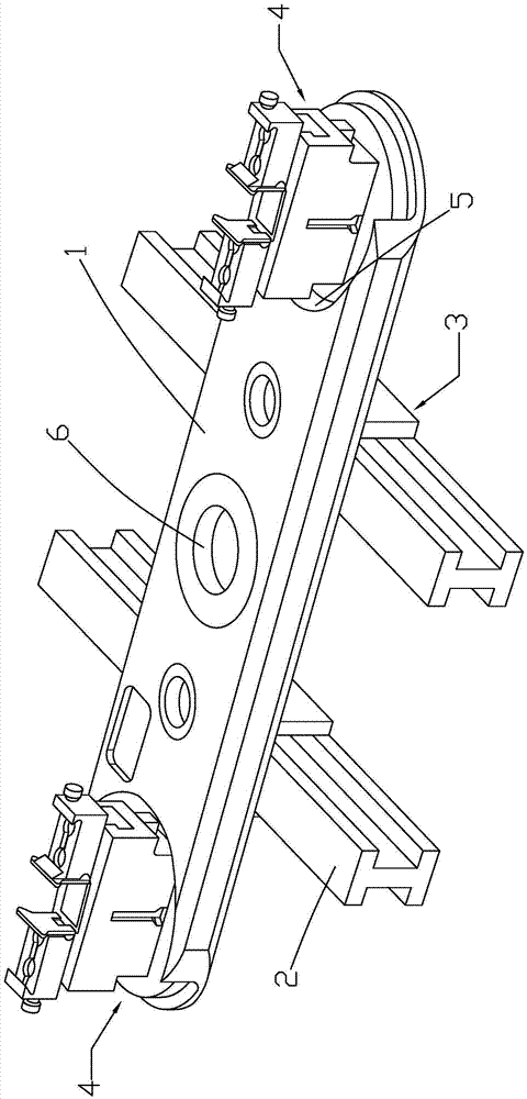
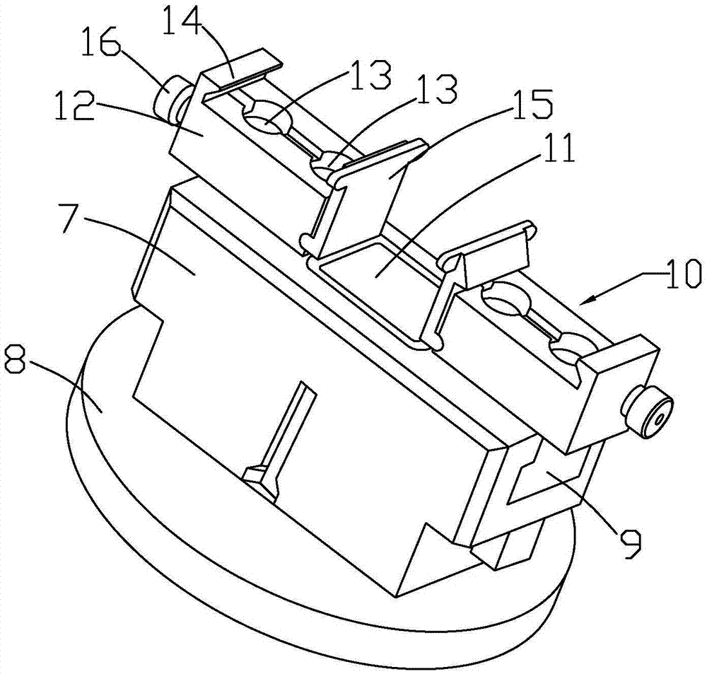
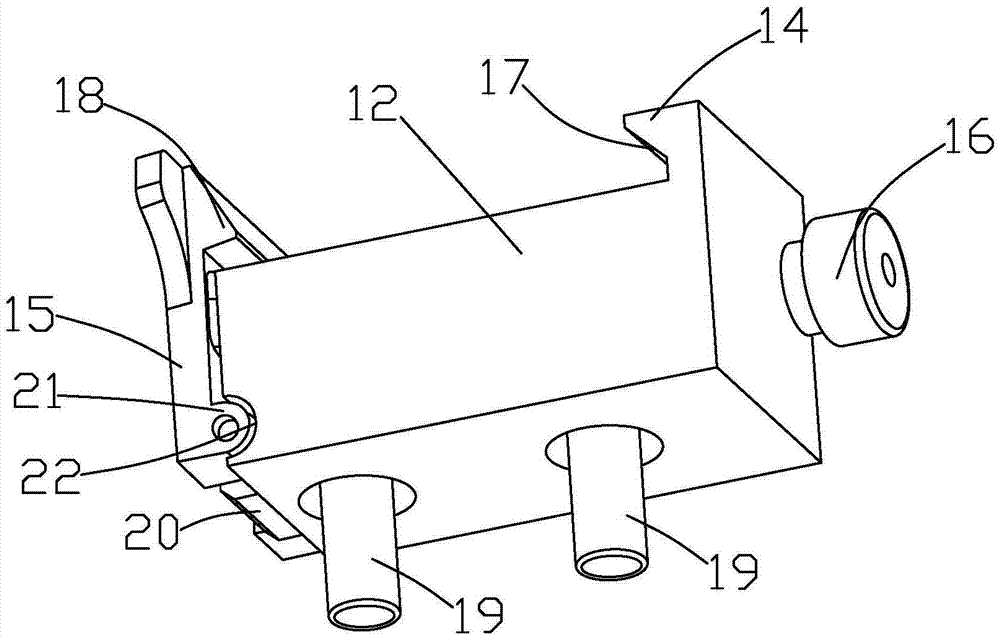
[0028] like Figure 1 to Figure 5As shown, it is a locking device for mechanical parts processing according to the present invention, which includes a supporting positioning plate 1, an I-shaped guide rail 2, a sliding mechanism 3 and a locking system 4, and the supporting positioning plate 1 is moved and connected to the I-shaped On the type guide rail 2, the sliding mechanism 3 includes a horizontal plate 27, a turntable 31 and two sets of limit mechanisms. The turntable 31 is rotatably connected to the top surface of the horizontal plate 27. The top surface of the turntable 31 is provided with a column 32, and the end of the column 32 The end cover 33 is arranged on the top, and the column 32 is matched with the positioning hole 6. The turntable 31 can drive the support positioning plate 1 to rotate together through the column 32 and the end cover 33, which increases the working radius of the support positioning plate 1 and simplifies the process of assembly line production....


PUM


Abstract

The invention discloses a locking device for machining mechanical parts. The locking device for machining mechanical parts comprises a supporting and positioning plate, an H-shaped guide track, a sliding mechanism and a locking system, wherein the supporting and positioning plate is movably connected to the H-shaped guide track through the sliding mechanism; a positioning hole and annular slots are formed in the supporting and positioning plate; the annular slots are symmetrically distributed in two sides of the positioning hole; the locking system comprises rotating chucks, positioning bases and locking mechanisms; each rotating chuck is rotatably connected to the inside of the corresponding annular slot; each positioning base is fixedly connected to the corresponding rotating chuck; a chute is formed in the top surface of each positioning base; and each locking mechanism is movably connected to the corresponding positioning base through a boosting plate. The locking device for machining mechanical parts is simple in structure and high in practicality; the distance between the two locking mechanisms can be adjusted to lock a mechanical part, and furthermore, the mechanical part can be locked by the independent locking mechanisms; locking machining of mechanical parts with different sizes and specifications can be implemented; and operability of the locking device is improved.

Description

technical field [0001] The invention relates to a locking device for processing mechanical parts. Background technique [0002] Locking devices are widely used in the field of mechanical parts processing. They mainly play the role of clamping and locking mechanical parts to prevent mechanical parts from rotating or moving during processing, which will affect the final processing quality and effect. [0003] In the prior art, the locking device is directly fixed on the machine tool, and the locking device cannot be moved, which limits the working range of the locking device, and can only clamp mechanical parts of the same size, and cannot process mechanical parts of other sizes. Poor practicality and poor operability. Contents of the invention [0004] The purpose of the present invention is to provide a technical solution of a locking device for mechanical parts processing in view of the deficiencies in the prior art, which can not only adjust the distance between the two...

Claims


Application Information

Patent Timeline
Patent Type & Authority Applications(China)
IPC IPC(8): B23Q3/06
CPCB23Q3/061
Inventor 陈意
Owner SHENGZHOU YIHAI MOTOR PARTS FACTORY
Why Eureka
Try Eureka