Concrete stirring device

A mixing device and concrete technology, which is applied in the direction of cement mixing device, clay preparation device, unloading device, etc., can solve the problems of small extrusion force of extrusion support, low extrusion efficiency of extrusion block, low discharge efficiency, etc. To achieve the effect of improving the discharge efficiency, reducing the body stuck, and the discharge speed is fast

Inactive Publication Date: 2016-03-30
TAICANG LUNWEN MACHINERY CO LTD
View PDF6 Cites 0 Cited by
  • Summary
  • Abstract
  • Description
  • Claims
  • Application Information

AI Technical Summary

Problems solved by technology

[0003] The concrete mixer is an important part of the construction industry. The working principle of the concrete mixer is that the material enters the equipment through the feed port, and the stirring device rotates and stirs at a high speed, so that the material is continuously tumbling in all directions and mixed quickly, and finally the material is discharged through the discharge port. Concrete mixers in the prior art generally use extrusion brackets to extrude the extrusion blocks to achieve extrusion, but because the extrusion force of the extrusion brackets is small, the extrusion efficiency of the extrusion blocks is low, which eventually leads to The efficiency of discharging is low, it is easy to cause stuck phenomenon, and the performance is unstable, resulting in high cost of manpower and time, low economic benefits, and it is difficult to meet the requirements of modern industry for automation equipment

Method used


Image

  • Concrete stirring device

Examples


Embodiment Construction

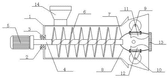
[0014] Such as figure 1 A concrete mixing device shown includes a housing 1, a power shaft 4, a stirring shaft 6, a driving extrusion wheel 9 and a driven extrusion wheel 10, and one end of the housing 1 is connected to the power shaft 4 through a bearing 2 and a sealing ring 3 One end of the power shaft 4 is connected to the motor 5, the other end of the power shaft 4 is connected to the stirring shaft 6, and the stirring shaft 6 is connected to a set of symmetrical brackets a7 and b8, the bracket a7 is provided with an active extrusion wheel 9, and the bracket b8 is provided with The driven extrusion wheel 10, the driving extrusion wheel 9 and the driven extrusion wheel 10 are respectively connected to the extrusion block a11 and the extrusion block b12, and both the extrusion blocks a11 and b12 are connected to the discharge plate arranged at the other end of the housing 1 13. The housing 1 is also provided with a feed port 14 .

[0015] Among them, the brackets a7 and b8 ...


PUM


Abstract

The invention discloses a concrete stirring device which comprises a shell, a power shaft, a stirring shaft, a driving extrusion wheel and a driven extrusion wheel. The power shaft is connected to one end of the shell through a bearing and a sealing ring. A motor is connected to one end of the power shaft, and the stirring shaft is connected with the other end of the power shaft. A set of support a and support b are connected to the stirring shaft symmetrically. The driving extrusion wheel is arranged on the support a, and the driven extrusion wheel is arranged on the support b. The driving extrusion wheel and the driven extrusion wheel are connected with an extrusion block a and an extrusion block b respectively. The extrusion block a and the extrusion block b are connected with a discharging plate arranged at the other end of the shell. The shell is further provided with a feed inlet. The concrete stirring device is simple in structure; the extrusion wheels are adopted for extrusion discharging, the extrusion intensity is high, and the middle of the extrusion block a and the middle of the extrusion block b are convex, so that material flowing is facilitated, the discharging speed is high, the discharging efficiency is effectively improved, the phenomenon that a device body gets stuck is reduced, and performance is stable.

Description

technical field [0001] The invention relates to the technical field of automation equipment in the construction industry, in particular to a concrete mixing device. Background technique [0002] With the rapid economic development in recent years, the civil construction industry is getting hotter and hotter, and the demand for concrete is increasing. Mixers are widely used in chemical, construction, food, environmental protection and other industrial production. From the perspective of their operation , Stirring can promote two or more than two kinds of materials to disperse and fully contact with each other, so as to achieve uniform density field, concentration field and temperature field. [0003] The concrete mixer is an important part of the construction industry. The working principle of the concrete mixer is that the material enters the equipment through the feed port, and the stirring device rotates and stirs at a high speed, so that the material is continuously tumbl...

Claims


Application Information

Patent Timeline
Patent Type & Authority Applications(China)
IPC IPC(8): B28C5/14B28C7/16B28C5/08
CPCB28C5/142B28C5/0806B28C7/16
Inventor 赵文刚
Owner TAICANG LUNWEN MACHINERY CO LTD
Why Eureka
Try Eureka