Roll compression device for bio-fuels

A compression device and biofuel technology, applied in the direction of material molding presses, presses, manufacturing tools, etc., can solve the problems of straw heat energy can not be used, aggravating environmental pollution, small gaps, etc.

Active Publication Date: 2016-03-30
CHONGQING HUAWANLUN BIOLOGICAL NEW ENERGY TECH CO LTD
View PDF7 Cites 4 Cited by
  • Summary
  • Abstract
  • Description
  • Claims
  • Application Information

AI Technical Summary

Problems solved by technology

Our country is a large agricultural country, and a large amount of straw is burned in the farmland every year, which not only aggravates the environmental pollution, such as the frequent occurrence of smog weather, but also wastes energy, the heat energy of the straw cannot be used, and the straw cannot be fully and effectively used. Utilization mainly lies in the electrification of rural life. People no longer rely on straw for cooking, so there is too much surplus. Straw is directly used in industrial production, and its energy per unit volume cannot meet its heat energy requirements. In order to make full use of straw For the above problems, our country vigorously advocates the remanufacturing of straw to meet the needs of industrial production. Now it is mainly crushed and pressed into high-density particles to increase the heat energy per unit volume. Extrusion technology is used in the existing technologies to form solid After the particles are piled up, the gaps are small, and the airflow is not smooth after being filled into the boiler, which affects combustion, and the accumulation of burnt ash is denser, which also affects combustion. This still needs to be solved by further innovation

Method used


Image

  • Roll compression device for bio-fuels
  • Roll compression device for bio-fuels

Examples


Embodiment Construction

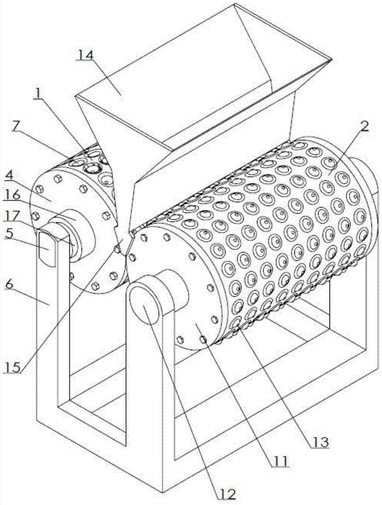
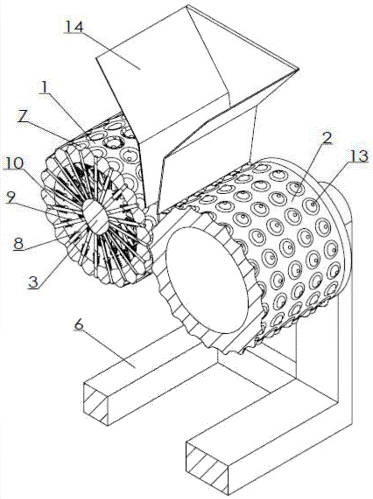
[0011] Examples of the present invention figure 1 , 2 As shown, the biofuel roller compression device is provided with a synchronous main roller 1 and a synchronous roller 2 with opposite rotation directions; the main roller is cylindrical, and a fixed shaft is provided at the axial center, and the middle section of the shaft is aligned with the main roller The position is the camshaft 3 with a downward protruding part, the two ends of the shaft are the optical axis 17 coaxial with the main roller, the optical axis is sleeved with a bushing 16, and the bushing is connected with the main end connected with the end surface of the main roller Plate 4, the optical axis at both ends is connected with positioning shaft 5, the positioning shaft has a flat surface and is fixedly connected with bracket 6, the surface of the main roller is provided with depressions 7 distributed in the circumferential direction, and the bottom of the depression is provided with holes through the side wa...


PUM


Abstract

The invention discloses a roll compression device for bio-fuels. The roll compression device for the bio-fuels is characterized by comprising a main roll and a synchronous roll, wherein the main roll is barrel-shaped; a fixed shaft rod is arranged at an axis position; a cam shaft with a downwards-projecting part is arranged at a position aligned with the main roll, of the middle section of the shaft rod; polished shafts coaxial with the main roll are arranged at the two ends of the shaft rod; a shaft sleeve sleeves each polished shaft; each shaft sleeve is connected with a main end plate connected with the corresponding end surface of the main roll; the polished shafts at the two ends are connected with a location shaft respectively; each location shaft is fixedly connected with a support; peripherally-distributed recessions are arranged on the surface of the main roll; a hole penetrating through the sidewall of the main roll is arranged in the bottom of each recession; an ejection rod is fitted in each hole; and the inner end of each ejection rod is ejected onto the cam shaft. According to the invention, the pressed and broken particles have large gaps after being accumulated, a gas flow is smooth and combustion is vigorous after a boiler is filled with the particles, and moreover, the gaps can be furthest reserved through thoroughly combusting thin ash, thus promoting combustion.

Description

technical field [0001] The invention relates to biofuel pressing equipment, in particular to a biofuel roller compression device. Background technique [0002] With the vigorous development of the economy and the progress of social production, the excessive consumption of energy has caused huge damage to the environment on which human beings depend, and it is imminent to find new clean and renewable alternative energy sources. Our country is a large agricultural country, and a large amount of straw is burned in the farmland every year, which not only aggravates the environmental pollution, such as the frequent occurrence of smog weather, but also wastes energy, the heat energy of the straw cannot be used, and the straw cannot be fully and effectively used. Utilization mainly lies in the electrification of rural life. People no longer rely on straw for cooking, so there is too much surplus. Straw is directly used in industrial production, and its energy per unit volume cannot...

Claims


Application Information

Patent Timeline
Patent Type & Authority Applications(China)
IPC IPC(8): B30B11/16B30B15/32
CPCB30B11/16B30B11/165B30B15/32
Inventor 赵正美
Owner CHONGQING HUAWANLUN BIOLOGICAL NEW ENERGY TECH CO LTD
Why Eureka
Try Eureka