Gas pumping-injecting interactive type foundation pit precipitation system and precipitation method thereof

An interactive, foundation pit technology, applied in excavation, infrastructure engineering, construction, etc., can solve problems such as affecting drainage efficiency, affecting the water output of dewatering wells, increasing the difficulty of tube well protection, and improving drainage efficiency.

Inactive Publication Date: 2016-03-30
SHANGHAI GUANGLIAN ENVIRONMENTAL & GEOTECHNICAL ENG CO LTD
View PDF6 Cites 11 Cited by
  • Summary
  • Abstract
  • Description
  • Claims
  • Application Information

AI Technical Summary

Problems solved by technology

[0003] However, in soft soil areas, the soil properties change greatly. When the bottom of the excavation surface of the foundation pit is near the bottom of the aquifer or the aquifer is thin or there is a local lens in the excavation range, it is difficult for the tube well to fully exert its effect, and it is easy to aquitard formation
At the same time, for low-permeability soil layers, the influence range of dewatering wells is small, and it is difficult to reduce the water content of the soil layer. The corresponding tube well spacing is relatively small, which will affect earthwork excavation and increase the difficulty of tube well protection.
[0004] Vacuuming can improve the dewatering effect to a certain extent, but for low-permeability soil layers, with the continuation of vacuum pumping, the permeability of the soil layer around the dewatering well decreases sharply, which affects the water output of the dewatering well. Directly affect the drying efficiency

Method used


Image

  • Gas pumping-injecting interactive type foundation pit precipitation system and precipitation method thereof

Examples


Embodiment Construction

[0018] The embodiments of the present invention are described in further detail below in conjunction with the accompanying drawings, but the present embodiments are not intended to limit the present invention. All similar structures and similar changes of the present invention should be included in the scope of protection of the present invention. The commas in all indicate the relationship between and.

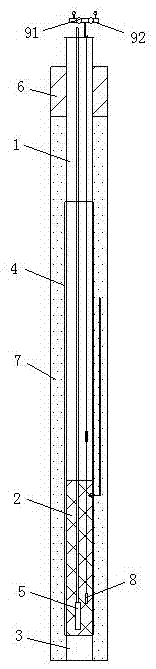
[0019] Such as figure 1 As shown, a gas pumping interactive foundation pit dewatering system provided by an embodiment of the present invention is characterized in that it includes at least two pumping interactive dewatering units;

[0020] The suction-injection interactive dewatering unit includes well pipes, filter pipes, sedimentation pipes, spacers, air extraction gate valves, gas injection gate valves, and vacuum pumps, and the well pipes, filter pipes, and sedimentation pipes are all vertically placed in the soil layer of the foundation pit , and the filter tube is loc...


PUM


Abstract

The invention discloses a gas pumping-injecting interactive type foundation pit precipitation system and a precipitation method thereof, relates to the technical field of civil engineering construction, and aims to improving dewatering efficiency of a low-permeability soil layer. The system comprises at least two pumping-injecting interactive precipitation units, wherein each pumping-injecting interactive precipitation unit comprises a well tube, a filter tube, a precipitation tube, a gas pumping gate valve, a gas injecting gate valve and a vacuum pump which are sequentially connected in series from top to bottom, wherein a submersible pump and a liquid level meter are arranged in the filter tube; the upper-end tube opening of the well tube is sealed by a well lid; the vacuum pump is connected to a gas hole in the well lid by virtue of the gas pumping gate valve; a high-pressure gas source is connected to the gas hole in the well lid by virtue of the gas injecting gate valve; each pumping-injecting interactive precipitation unit is used as a strong vacuum tube well for precipitating a foundation pit soil body; and when water yield of each pumping-injecting interactive precipitation unit is obviously reduced, each pumping-injecting interactive precipitation unit is converted into a gas injecting well for use. The system and the method provided by the invention are especially suitable for precipitation of the low-permeability soil layer.

Description

technical field [0001] The invention relates to civil construction technology, in particular to a technology of a gas pumping interactive foundation pit dewatering system and a dewatering method thereof. Background technique [0002] In order to provide a dry and safe construction environment for deep foundation pit engineering, it is very necessary to reduce the groundwater level of the excavated soil layer and the aquifer that may cause the confined water surge of the foundation pit floor by means of precipitation. In deep foundation pit engineering in soft soil areas, due to the deep excavation depth, tube wells are generally used to reduce the water level or water content in the aquifer. [0003] However, in soft soil areas, the soil properties change greatly. When the bottom of the excavation surface of the foundation pit is near the bottom of the aquifer or the aquifer is thin or there is a local lens in the excavation range, it is difficult for the tube well to fully ...

Claims


Application Information

Patent Timeline
Patent Type & Authority Applications(China)
IPC IPC(8): E02D19/10E02D17/04
CPCE02D17/04E02D19/10
Inventor 陆建生乔华山缪俊发沈驰刘中浩邱鹰刘国友
Owner SHANGHAI GUANGLIAN ENVIRONMENTAL & GEOTECHNICAL ENG CO LTD
Why Eureka
Try Eureka