
A portable vehicle oil circulation device and its working method

A circulatory device, portable technology, applied in vehicle maintenance, vehicle maintenance/repair, fluid pressure actuation devices, etc., can solve the problems of difficulty in removing air from pipelines, cab oil pollution, long hydraulic pipeline laying, etc. The effect of facilitating outdoor operations, reducing labor intensity and preventing pollution

Active Publication Date: 2018-10-16
浙江省送变电工程有限公司 +2
View PDF9 Cites 0 Cited by
  • Summary
  • Abstract
  • Description
  • Claims
  • Application Information

AI Technical Summary

Problems solved by technology

This method is only suitable for maintenance in the factory area, and it is easy to cause oil pollution in the cab, making cleaning difficult
Especially for the oil circuit of the passenger car clutch control system and the oil circuit of the throttle system of the automobile crane platform, due to the long and complicated laying of the hydraulic pipelines, it is particularly difficult to remove the air from the pipelines

Method used


Image

  • A portable vehicle oil circulation device and its working method
  • A portable vehicle oil circulation device and its working method
  • A portable vehicle oil circulation device and its working method

Examples


Embodiment Construction

[0027] The technical solution of the present invention will be further described in detail below in conjunction with the accompanying drawings.

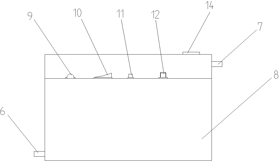
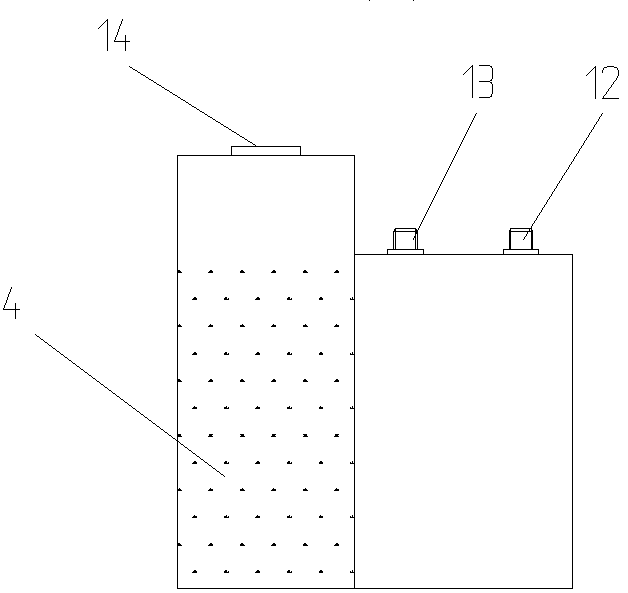
[0028] Such as figure 1 , 2 As shown, the present invention includes a hydraulic system and an electrical system,

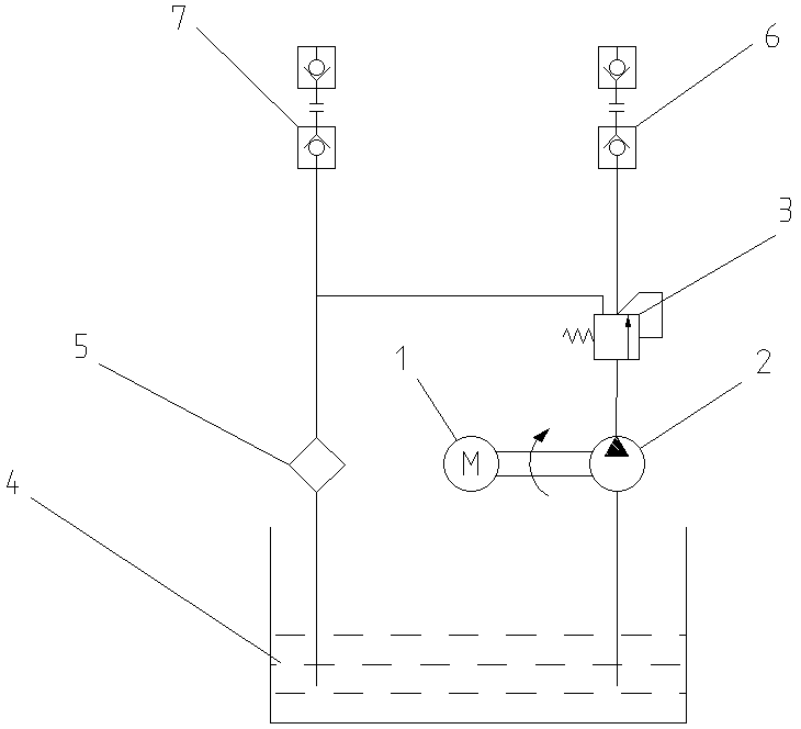
[0029] The hydraulic system, such as image 3 As shown, it includes a motor 1, a hydraulic pump 2, a valve 3, a first interface 6, a second interface 7 and an oil tank 4. The hydraulic pump 2 is connected to the motor 1, and the oil outlet of the hydraulic pump 2 is connected to the valve 3 through the oil pipe. The oil port is connected, the oil outlet of the valve 3 is connected with the first port 6 through the oil pipe, the pressure relief port of the valve 3 is connected with the oil return pipeline and directly returns to the fuel tank 4, and the second port 7 is connected with the fuel tank 4; the first port 6 is located at the lower part of the fuel tank 4; the first interface 6 is located at the upper part o...


PUM


Abstract

The invention discloses a portable vehicle oil line circulating device and a working method thereof and relates to a vehicle overhauling device. In an oil line of a coach clutch operation system and an oil line of a lifting platform accelerator system of an automobile crane, air is particularly hard to exhaust from pipelines because long hydraulic pipelines of the oil lines are laid and are relatively complicated. The device disclosed by the invention comprises a hydraulic system and an electric system, wherein the hydraulic system comprises an electro-motor, a hydraulic pump, an overflowing valve, a first interface, a second interface and an oil tank; the hydraulic pump is connected with the electro-motor; an oil outlet of the hydraulic pump is connected with an oil inlet of the overflowing valve through an oil pipe; the oil outlet of the overflowing valve is connected with the first interface through the oil pipe; a pressure relief hole of the overflowing valve is connected with an oil returning pipeline; the second interface is connected with the oil tank; the first interface is arranged at the lower part of the oil tank; the second interface is arranged at the upper part of the oil tank; a returned oil filter connected with the second interface is arranged inside the oil tank; the electric system comprises a power switch, a positive terminal and a negative terminal. The device disclosed by the invention is simple in structure, capable of alleviating the labor intensity of a worker, and flexible and convenient to operate.

Description

technical field [0001] The invention relates to a vehicle maintenance device, in particular to a portable vehicle oil circuit circulation device. Background technique [0002] At present, the clutch control system of heavy goods vehicles, passenger cars and other vehicles and the accelerator system of the suspension platform of automobile cranes are all controlled by hydraulic system. Taking passenger cars as an example, the clutch control system uses the driver's foot to step on the clutch master cylinder pedal to form pressure in the clutch control system, open the clutch sub-pump oil valve, and introduce high-pressure air into the vehicle's air circuit system to push the piston in the clutch sub-pump to move. Thereby pushing the clutch fork to impel the clutch to disengage. However, after the vehicle clutch control system breaks down and needs to replace its clutch master cylinder or sub-cylinder, it is difficult to remove the air in the hydraulic line. At present, ther...

Claims


Application Information

Patent Timeline
Patent Type & Authority Patents(China)
IPC IPC(8): F15B21/04B60S5/00
CPCB60S5/00F15B21/041F15B21/044
Inventor 王泽秋陈国其宋彧陈虎儿
Owner 浙江省送变电工程有限公司
Learn More