Sliding sleeve

A technology for sliding sleeves and steering shafts, which is applied in the direction of motor vehicles, linear motion bearings, and rotating parts that resist centrifugal force. The effect of reducing friction

Inactive Publication Date: 2016-03-30
THYSSENKRUPP PRESTA AG
View PDF8 Cites 5 Cited by
  • Summary
  • Abstract
  • Description
  • Claims
  • Application Information

AI Technical Summary

Problems solved by technology

Both bearings are complex to produce and require a high surface quality of the parts that are movable relative to each other
Therefore, these bearings are not suitable for the support of telescopic steering shafts

Method used


Image

  • Sliding sleeve
  • Sliding sleeve
  • Sliding sleeve

Examples


Embodiment Construction

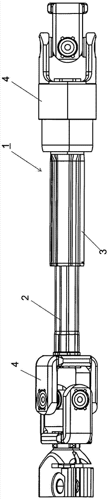
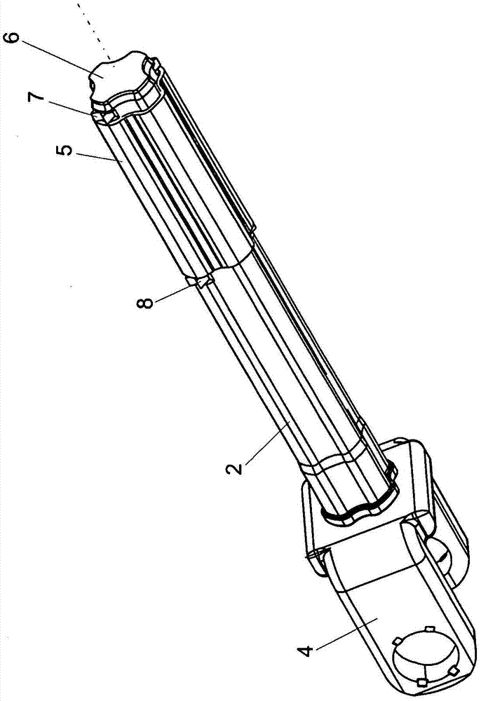
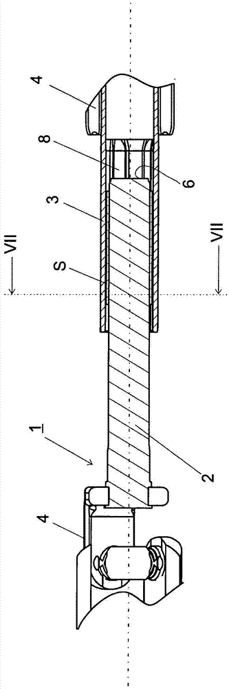
[0028] exist figure 1 A side view of the telescoping steering shaft 1 is shown in . The steering shaft 1 includes an inner shaft 2 and an outer shaft 3 . The inner shaft 2 is provided with a non-circular, in this example roughly cloverleaf-shaped cross-section. The outer shaft 3 is tubular in shape and has a hollow cross-section which is complementary to the outer peripheral contour of the inner steering shaft. The inner shaft 2 and the outer shaft 3 each carry on the end faces a connecting piece 4 known per se for a universal joint for connecting a steering gear with a steering column. In this example, a universal joint is shown as joint, in which a pin (pin cross) of the universal joint crosshead is mounted rotatably in a connection part 4 designed as a fork, wherein the fork The support structures of the shape are vertically offset from each other, but it is conceivable and possible that other joints or entirely different elements are connected to the telescoping shaft p...


PUM

PropertyMeasurementUnit
diameteraaaaaaaaaa

Abstract

The invention relates to a telescopable steering spindle (1) having an inner spindle (2) and an outer spindle (3), which are arranged coaxially in relation to one another and have an out-of-round cross section for torque transmission, wherein an intermediate space is provided between the outer spindle (3) and the inner spindle (2), a sliding sleeve (5) being arranged in the said intermediate space, wherein the sliding sleeve (5) is provided with a surface structuring (11) on at least one surface facing the inner spindle (2) or the outer spindle (3).

Description

[0001] This application is a divisional application of an application with an international filing date of September 25, 2009, a national application number of 200980147247.3 (international application number of PCT / EP2009 / 006946), and an invention title of "sliding sleeve". technical field [0002] The invention relates to a sliding sleeve for use between two structural elements which can be nested or rotatably inserted into one another, as well as a telescoping steering shaft, and a method for producing the sliding sleeve. Background technique [0003] The sliding sleeve is used to reduce friction and / or to compensate, for example, play between the relatively rotatable and telescopic bushings and the play between the outer and inner shafts of the telescoping steering shaft. [0004] The telescoping steering shaft has two coaxial shaft parts which have a non-circular cross-section and are axially movable but capable of transmitting torque. In steering shafts it is important...

Claims


Application Information

Patent Timeline
Patent Type & Authority Applications(China)
IPC IPC(8): F16C3/035F16C29/02F16C33/20B29C59/04B62D1/16
CPCB29C59/04B62D1/16F16C3/035F16C29/02F16C33/201B29C59/043B62D1/185B62D1/20F16C33/20F16D3/06F16D2300/10F16C2326/24F16C2220/02F16C2220/44F16C2220/04F16C33/208F16C2220/48Y10T29/49471Y10T403/7026
Inventor 安德烈亚斯·普里茨勒尔
Owner THYSSENKRUPP PRESTA AG
Why Eureka
Try Eureka