
Garbage gasification boiler and application method thereof

A gasification boiler and gasification furnace technology, applied in the direction of incinerators, combustion methods, climate sustainability, etc., can solve the problems of low energy utilization rate, secondary pollution, inconvenient maintenance and use, etc., to improve energy utilization efficiency, ensure internal pressure, and reduce emissions

Active Publication Date: 2016-03-30
卢国全
View PDF11 Cites 3 Cited by
  • Summary
  • Abstract
  • Description
  • Claims
  • Application Information

AI Technical Summary

Problems solved by technology

[0012] Existing waste gasification reactors often pay more attention to the effect of waste gasification treatment, but do not do well in the full utilization of resources, and the energy utilization rate is not high
Moreover, most of the existing garbage gasification reactors still have problems such as inconvenient maintenance and use, high cost of use, incomplete treatment of flue gas, easy to cause secondary pollution, and inability to operate continuously.

Method used


Image

  • Garbage gasification boiler and application method thereof
  • Garbage gasification boiler and application method thereof

Examples


Embodiment 1

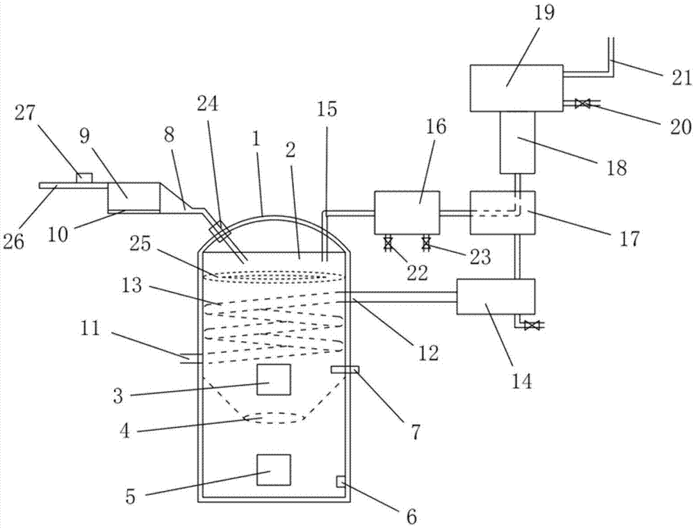
[0048] like figure 1 As shown, an embodiment of the waste gasification boiler of the present invention includes a waste gasification device and a gas processing device. Among them, the refuse gasification device includes a gasification furnace body 1 and a furnace chamber 2 provided in the gasification furnace body 1 . The upper part of the furnace chamber 2 is provided with a steam collecting pipe 25, and a small amount of water vapor is generated by the steam collecting pipe 25 to supply the water vapor required for the gasification of the garbage in the furnace chamber 2. The lower part of the furnace chamber 2 is provided with a lower ash port 4, a gasification medium input port 6 is provided below the lower ash port 4, and an igniter 7 is provided above. The upper part of the gasification furnace body 1 is also provided with a gas gas collecting pipe 15 . The gas treatment device of the waste gasification boiler includes an oil-water separator 16 , a gas waste heat reco...

Embodiment 2

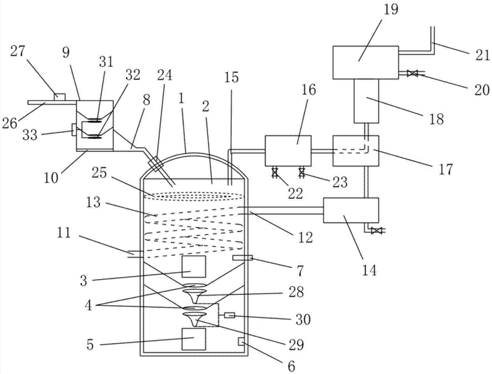
[0055] like figure 2 As shown, an embodiment of the waste gasification boiler of the present invention includes a gasification furnace body 1 and a furnace chamber 2 arranged in the gasification furnace body 1 . A gas gas collecting pipe 15 is arranged on the upper side wall of the gasification furnace body 1, and the gas gas collecting pipe 15 is connected to a gas processing device, and the gas processing device includes an oil-water separator 16, a gas waste heat recovery device 17, and a spraying device connected in sequence. Dust suppression device 18 and air purification processor 19. Among them, the oil-water separator 16 is connected to the gas collecting pipe 15, the air purification processor 19 is provided with a gas outlet 20 and a smoke exhaust pipe 21, the smoke exhaust pipe 21 is a PVC plastic pipe, and the bottom of the oil-water separator 16 is provided with a water outlet 22 and a smoke exhaust pipe 21. Drain port 23. The lower part of the furnace chamber ...


PUM


Abstract

The invention discloses a garbage gasification boiler and an application method of the garbage gasification boiler. The garbage gasification boiler comprises a gasification boiler body (1), wherein a hearth (2) is arranged in the gasification boiler body (1), ash discharging outlets (4) are formed in the lower portion of the hearth (2), and a steam collecting pipe (25) is arranged on the upper portion of the hearth (2). The garbage gasification boiler further comprises a gasification boiler waste heat recovery device. The gasification boiler waste heat recovery device comprises a water inlet (11), a water outlet (12), a heat exchange coil pipe (13) and a water storage tank (14), wherein the heat exchange coil pipe (13) is installed inside the hearth (2), and the water storage tank (14) is connected with the water outlet (12). The garbage gasification boiler is high in energy utilization rate and low in cost, convenient to use and repair, and clean and environmentally friendly.

Description

technical field [0001] The invention belongs to the field of garbage disposal equipment, and in particular relates to a garbage gasification boiler and an application method thereof. Background technique [0002] With the continuous improvement of living standards, people's material consumption is increasing day by day. Correspondingly, domestic waste has also increased sharply, which has brought heavy pressure on the ecological environment. Garbage is not only a source of pollution, but also contains renewable resources and energy. How to deal with these garbage has become a common problem faced by countries all over the world. [0003] Gasification of domestic waste is a new type of waste treatment technology. Compared with incineration, landfill and composting treatment methods, gasification treatment technology has attracted more and more attention due to its advantages of cleanliness, environmental protection and resource reuse. People strive to use gasification tech...

Claims


Application Information

Patent Timeline
Patent Type & Authority Applications(China)
IPC IPC(8): F23G5/027F23G5/033F23G5/46
CPCF23G5/0276F23G5/033F23G5/46F23G2201/40F23G2201/80F23G2206/203Y02E20/12Y02P80/15
Inventor 卢国全
Owner 卢国全
Learn More