Method for intelligently controlling water temperature of solar energy system with multiple parameters

A technology of intelligent control and solar energy, applied in the field of solar energy, can solve the problems of low degree of automation of solar collectors and not many researches on intelligent control of collectors, etc., to achieve the best heat exchange effect and improve the effect of intelligence

Inactive Publication Date: 2016-03-30
SHANDONG UNIV OF TECH
3 Cites 6 Cited by

AI-Extracted Technical Summary

Problems solved by technology

[0004] At present, the degree of automation of solar heat collectors is not high. Although the prior art has also studied the intelligent control of solar energy, there are not many researches on the intellig...

Method used

As preferably, described inner fin 15 is a straight plate shape, and the extension direction of inner fin 15 is along the flow direction of fluid evaporation, that is, along the heat-absorbing end 9 to the direction of the heat-dissipating end, or in other words along the collector Axial movement of the heat-absorbing end 9 of the heat pipe. Through such arrangement, the fluid space formed between the inner fins is consistent with the flow direction of the fluid, thereby reducing flow resistance and increasing heat absorption at the same time.
Because find by experiment, heat-collecting pipe heat-absorbing end is most heat-absorbing in the middle part, from middle part to both sides, heat-absorbing becomes smaller gradually, therefore by arranging the interior fin 15 height variation of heat-collecting pipe, makes heat-collecting pipe absorb heat like this The heat-absorbing area at the end is the largest in the middle and the smallest on both sides, so that the heat-absorbing capacity in the middle is the largest, which conforms to the heat-absorbing law of the heat-absorbing end of the heat-collecting tube, makes the heat-absorbing end of the heat-collecting tube as a whole absorb heat evenly, and avoids heat-absorbing of the heat-collecting tube The local temperature at the end is overheated, resulting in poor heat dissipation effect and shortening the service life of the heat-absorbing end of the heat-collecting tube.
By arranging communication hole 6, guarantee the communication between adjacent small channels 10, thereby make the fluid in the big small channels of pressure can flow in the small small channels of adjacent pressure, solve the situation of flat tube heat exchange The problem of uneven internal pressure and excessive local pressure can promote the full flow of fluid in the heat exchange channel, improve the heat exchange efficiency, and also increase the service life of the heat collecting tube.
By monitoring the height of the water level, avoid the water level in the water tank being too low, thereby causing heat collecting tube 1 heat release end 10 to be unable to dissipate heat, causing heat collecting tube damage, avoiding the water level in the water tank 8 is too high simultaneously, thereby causing the pressure in the water tank to be too high Great, especially when heated to a boil.
[0054] As a preference, along the direction of the side wall 12...

Abstract

The invention provides an intelligent control method for a solar energy system. A solar heat collector system comprises a heat collector, wherein the heat collector comprises a heat collecting pipe and a water tank; the heat collecting pipe comprises a heat absorbing end and a heat releasing end, and the heat releasing end is arranged in the water tank; a water level meter is arranged in the water tank, and an outlet pipe temperature sensor is arranged on an outlet pipeline of the water tank; an inlet pipe valve and an outlet pipe valve are respectively arranged on an inlet pipe and an outlet pipe of the water tank, and the water level meter, the temperature sensor, the inlet pipe valve and the outlet pipe valve are in data connection with a central controller; the central controller controls the size of the opening degree of the inlet pipe valve and the outlet pipe valve according to the temperature measured by the temperature sensor and the water level measured by the water level meter. The method automatically controls multiple parameters of the solar energy system, realizes intelligent control for the solar water temperature, and therefore improves the using intelligentization of the solar energy system.

Application Domain

Technology Topic

Image

  • Method for intelligently controlling water temperature of solar energy system with multiple parameters
  • Method for intelligently controlling water temperature of solar energy system with multiple parameters
  • Method for intelligently controlling water temperature of solar energy system with multiple parameters

Examples

  • Experimental program(5)

Example Embodiment

[0098] 1. Example One
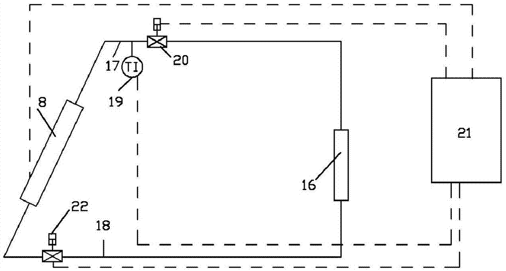
[0099] As an improvement, a temperature sensor is provided in the water tank 8 for measuring the temperature of the water in the water tank 8. The inlet pipe 18 and the outlet pipe 17 of the water tank 8 are respectively provided with an inlet pipe valve 22 and an outlet pipe valve 20. The temperature sensor, the inlet pipe valve 22 and the outlet pipe valve 20 are in data connection with the central controller 21. The central controller 21 controls the opening and closing of the inlet pipe valve 22 and the outlet pipe valve 20 and the size of the opening according to the temperature measured by the temperature sensor.
[0100] If the temperature of the water in the water tank 8 measured by the temperature sensor is lower than the lower limit value, the central controller 21 controls the valves 20 and 22 to automatically close, thereby ensuring that the water in the water tank 8 continues to heat up; if the measured water in the water tank 8 If the temperature exceeds the upper limit value, the central controller 21 controls the valves 20 and 22 to open automatically. Through the above measures, it can be ensured that the temperature of the water output from the water tank 8 remains at a certain temperature, so that it can reach a usable temperature.
[0101] Preferably, multiple temperature sensors are provided in the water tank 8, and the temperature of the water is measured by the multiple temperature sensors.
[0102] Preferably, the central controller 21 controls the opening and closing of the valves 20 and 22 by the average value of the water temperature measured by a plurality of temperature sensors.
[0103] Preferably, the central controller 21 controls the opening and closing of the valves 20 and 22 through the lowest value of the water temperature measured by the plurality of temperature sensors. By taking the lowest value, it can be ensured that the temperature of the water at all positions in the water tank 8 can reach the usable temperature.
[0104] Preferably, the at least one temperature sensor is arranged in the water tank 8 near the inlet pipe 18 of the water tank.
[0105] Preferably, the at least one temperature sensor is arranged in the water tank 8 near the outlet pipe 17 of the water tank.

Example Embodiment

[0106] 2. Example two
[0107] As an improvement, the central controller 21 controls the opening of the valves 20 and 22 to ensure that the temperature of the outlet water in the water tank reaches a constant value. That is, the temperature of the outlet water of the water tank 8 is adjusted by adjusting the flow rate into and out of the water tank 8.
[0108] An outlet pipe temperature sensor 19 is provided on the water tank outlet pipeline 17, and the outlet temperature sensor 19 is in data connection with the central controller 21. The central controller 21 controls the inlet pipe valve 22 and the outlet pipe valve according to the temperature measured by the temperature sensor 19 20 opening and closing and the size of the opening.
[0109] If the temperature of the water in the outlet pipe 19 measured by the temperature sensor 19 is lower than the lower limit value, the central controller 21 controls the opening of the valve 20 to increase and decrease the opening of the valve 22, so that the water entering the water tank 8 decreases, so that The water leaving the water tank 8 increases, so that the amount of water in the water tank 8 decreases. The temperature of the water in the water tank 8 is increased by reducing the amount of water, thereby increasing the outlet temperature of the water tank 8. On the contrary, if the temperature of the water in the outlet pipe 19 measured by the temperature sensor 19 is higher than the upper limit value, the central controller 21 controls the opening of the valve 20 to decrease and increase the opening of the valve 22, so that the water entering the water tank 8 increases. As a result, the water leaving the water tank 8 is reduced, and the amount of water in the water tank 8 is increased. The temperature of the water in the water tank 8 is reduced by the increase of the water volume, thereby reducing the outlet temperature of the water tank 8. Through the above measures, it can be ensured that the temperature of the water output from the water tank 8 is maintained within a certain range, so that the usable temperature can be reached.
[0110] Preferably, the outlet pipe 17 is provided with a plurality of temperature sensors 19, and the temperature of the water in the outlet pipe of the water tank is measured by the plurality of temperature sensors 19.
[0111] Preferably, the central controller 21 controls the opening degree of the valves 20 and 22 by the average value of the water temperature measured by the plurality of temperature sensors 19.
[0112] Preferably, the central controller 21 controls the opening degree of the valves 20 and 22 through the lowest value of the water temperature measured by the plurality of temperature sensors 19. By taking the lowest value, further accuracy of the data can be achieved.
[0113] Preferably, the at least one temperature sensor is arranged at a position where the outlet pipe 17 is close to the water tank 18.
[0114] Preferably, the upper limit value minus the lower limit value is 5-10 degrees Celsius, preferably 6-8 degrees Celsius.

Example Embodiment

[0115] 3. Example Three
[0116] As a further improvement of the second embodiment, the opening and closing of the valves 20 and 22 are controlled by measuring the temperature of the water in the water tank 8.
[0117] If the temperature of the water in the water tank 8 measured by the temperature sensor 19 is lower than the lower limit value, the central controller 21 controls the opening of the valve 20 to increase and decrease the opening of the valve 22, so that the water entering the water tank 8 is reduced and leaving The water in the water tank 8 increases, so that the amount of water in the water tank 8 decreases. The temperature of the water in the water tank 8 is increased by reducing the amount of water, thereby increasing the outlet temperature of the water tank 8. On the contrary, if the temperature of the water in the water tank 8 measured by the temperature sensor 19 is higher than the upper limit value, the central controller 21 controls the opening of the valve 20 to decrease and increase the opening of the valve 22, so that the water entering the water tank 8 increases. As a result, the water leaving the water tank 8 is reduced, and the amount of water in the water tank 8 is increased. The temperature of the water in the water tank 8 is reduced by the increase of the water volume, thereby reducing the outlet temperature of the water tank 8. Through the above measures, it can be ensured that the temperature of the water output from the water tank 8 is maintained within a certain range, so that the usable temperature can be reached.
[0118] Preferably, multiple temperature sensors are provided in the water tank 8, and the temperature of the water is measured by the multiple temperature sensors.
[0119] Preferably, the central controller 21 controls the opening degree of the valves 20 and 22 by the average value of the water temperature measured by a plurality of temperature sensors.
[0120] Preferably, the central controller 21 controls the opening degree of the valves 20 and 22 through the lowest value of the water temperature measured by the plurality of temperature sensors. By taking the lowest value, it can be ensured that the temperature of the water at all positions in the water tank 8 can reach the usable temperature.
[0121] Preferably, the at least one temperature sensor is arranged in the water tank 8 near the inlet pipe 18 of the water tank.
[0122] Preferably, the at least one temperature sensor is arranged in the water tank 8 near the outlet pipe 17 of the water tank.
[0123] Preferably, the upper limit value minus the lower limit value is 8-13 degrees Celsius, preferably 9-11 degrees Celsius.
[0124] 4. Example Four
[0125] As an improvement, a water level gauge is provided in the water tank 8, and the water level gauge is data connected to the central controller 21. The central controller monitors the height of the water level to control the opening of the valves 20 and 22.
[0126] By monitoring the height of the water level, it is avoided that the water level in the water tank is too low, which will cause the radiating end 10 of the heat collection tube 1 to fail to dissipate heat and cause damage to the heat collection tube. At the same time, prevent the water level in the water tank 8 from being too high, thereby causing excessive pressure in the water tank, especially It is under heating and boiling.
[0127] If the water level of the water tank 8 measured by the water level gauge is higher than the upper limit value, the central controller 21 controls the opening of the valve 20 to increase and decrease the opening of the valve 22, so that the water entering the water tank 8 is reduced and leaving the water tank 8 The amount of water increases, so that the amount of water in the water tank 8 decreases. The water level in the water tank 8 is lowered by reducing the amount of water. On the contrary, if the water level in the water tank 8 measured by the water level gauge is lower than the lower limit value, the central controller 21 controls the opening of the valve 20 to decrease and increase the opening of the valve 22, so that the water entering the water tank 8 increases and leaving the water tank The water in 8 decreases, so that the amount of water in the water tank 8 increases.
[0128] Preferably, the upper limit value of the water level is the height at which 90%-95% of the water tank volume is located, preferably 93%.
[0129] Preferably, the lower limit value of the water level is the height at which the heat release end 10 of the heat collecting tube 1 extends into the water tank. So as to ensure that the water in the water tank fully covers the radiating end.

PUM

no PUM

Description & Claims & Application Information

We can also present the details of the Description, Claims and Application information to help users get a comprehensive understanding of the technical details of the patent, such as background art, summary of invention, brief description of drawings, description of embodiments, and other original content. On the other hand, users can also determine the specific scope of protection of the technology through the list of claims; as well as understand the changes in the life cycle of the technology with the presentation of the patent timeline. Login to view more.

Similar technology patents

Method for guiding to photograph and mobile terminal

ActiveCN103401994AResolve problems presented by the inability to articulate compositional ideas to othersImprove intelligenceTelevision system detailsDigital data processing detailsComputer engineeringMultimedia
Owner:GUANGDONG OPPO MOBILE TELECOMM CORP LTD

Classification and recommendation of technical efficacy words

  • Good heat transfer effect
  • Improve intelligence

Condenser and air conditioner comprising same

ActiveCN103604255AIncrease the effective heat transfer areaGood heat transfer effectEvaporators/condensersRefrigerantEngineering
Owner:TCL AIR CONDITIONER ZHONGSHAN CO LTD
Why Eureka
Try Eureka