A defect location device for ultrasonic testing

A positioning device, ultrasonic technology, applied to measuring devices, using sound waves/ultrasonic waves/infrasonic waves to analyze solids, using sound waves/ultrasonic waves/infrasonic waves for material analysis, etc. Accuracy and other issues, to avoid visual measurement errors and facilitate the flaw detection process

Active Publication Date: 2018-11-13
CRRC QIQIHAR ROLLING CO LTD
View PDF3 Cites 0 Cited by
  • Summary
  • Abstract
  • Description
  • Claims
  • Application Information

AI Technical Summary

Problems solved by technology

[0005] When finding the highest reflected wave of a defect, it is necessary to hold the probe and move the probe slightly near the defect position, and find out the highest point according to the change of the reflected wave. After finding the highest point, the reflected wave in the workpiece can be read on the oscilloscope screen. Position-related values, according to the relevant data displayed on the oscilloscope screen, the position of the defect is actually measured on the workpiece through a ruler. However, the flaw detection process is carried out continuously, and the ruler is not easy to carry. The ruler cannot be accurate to the center of the flaw detection, so the position of the defect is roughly measured by combining visual inspection and a ruler, so the operation has greater inaccuracy

Method used


Image

  • A defect location device for ultrasonic testing
  • A defect location device for ultrasonic testing
  • A defect location device for ultrasonic testing

Examples


Embodiment Construction

[0017] The present invention will be described in detail below in conjunction with the accompanying drawings and embodiments.

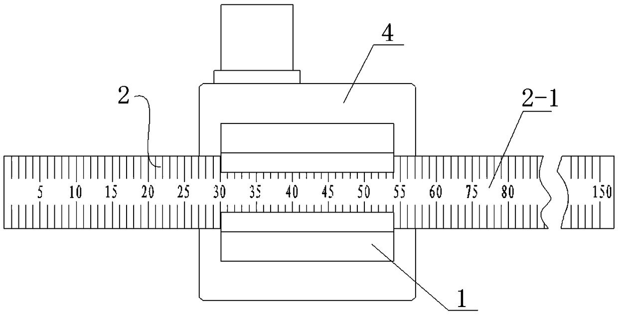
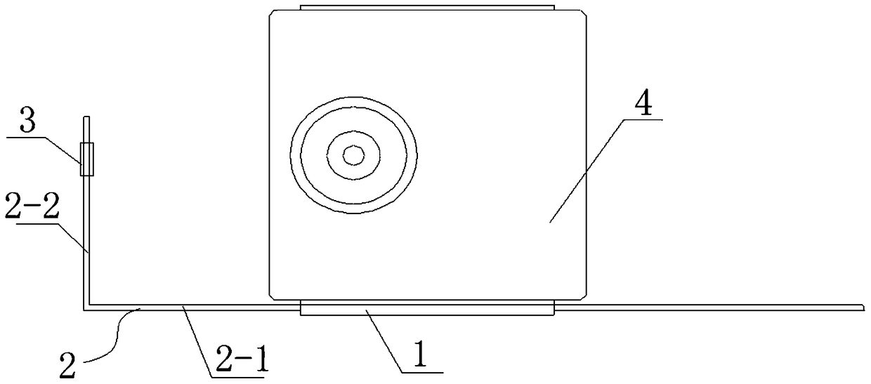
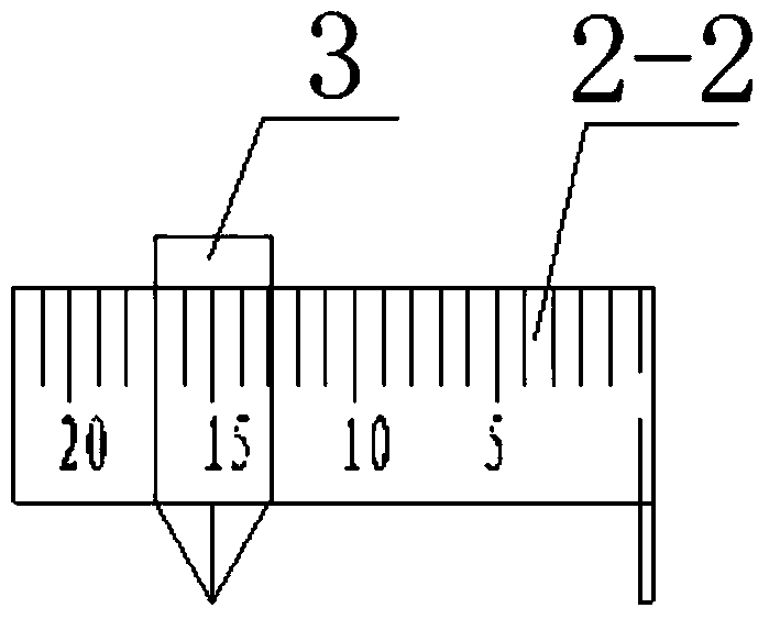
[0018] Such as figure 1 , figure 2 As shown, the present invention includes a mounting base 1 and a rectangular measuring ruler 2 . Wherein, the rectangular measuring ruler 2 comprises a first measuring ruler 2-1 and a second measuring ruler 2-2 fixedly connected to an end of the first measuring ruler 2-1, and the ruler surface of the second measuring ruler 2-2 It is perpendicular to the ruler surface of the first measuring ruler 2-1. A slideway is provided on the mounting base 1 , and the first measuring ruler 2 - 1 is slidably connected in the slideway of the mounting base 1 . Slide to set a movable arrow 3 on the second measuring ruler (such as figure 2 , image 3 shown).

[0019] Further, scale marks are respectively arranged on the first measuring ruler 2-1 and the second measuring ruler 2-2, and the measuring range of the first measuring...


PUM


Abstract

A related defect positioning apparatus applied to ultrasonic detection is characterized in that the apparatus comprises an installation mounting base and a right-angle measuring scale; the right-angle measuring scale comprises a first measuring scale and a second measuring scale fixedly connected with one end of the first measuring scale, and the scale surface of the first measuring scale is perpendicular to the scale surface of the second measuring scale; a slideway is disposed on the installation mounting base, and the first measuring scale is connected in the slideway in a sliding way; and the second measuring scale is provided with a flexible arrowhead in a sliding way. A double positioning manner in a plane is employed, and a point in a plane can be precisely positioned, a defect position is facilitated to be precisely determined, and defects are facilitated to be timely cleared and repaired.

Description

technical field [0001] The invention relates to a defect location device for ultrasonic detection. Background technique [0002] The basic principle of ultrasonic nondestructive testing is to use the material discontinuity caused by the existence of inhomogeneous defects in homogeneous materials. This discontinuity will produce interfaces of different sizes inside the material, resulting in inconsistencies in acoustic impedance. Ultrasonic waves will reflect on the interface (or "defect") of different acoustic impedances. Ultrasonic flaw detection uses the appearance of reflected waves at this interface to determine the position and size of defects in the workpiece. [0003] During ultrasonic testing, the reflected wave of the defect interface (the discontinuity of the material) will be displayed on the oscilloscope of the ultrasonic flaw detector. The oscilloscope can directly display the position and size of the reflected sound wave through the linear proportional relation...

Claims


Application Information

Patent Timeline
Patent Type & Authority Patents(China)
IPC IPC(8): G01N29/04G01N29/265G01N29/22
CPCG01N29/048G01N29/22G01N29/265
Inventor 李艳琴张瑞增刘霞高金平鲁关兴许静杨海林闫宝营刘江陈东波
Owner CRRC QIQIHAR ROLLING CO LTD
Why Eureka
Try Eureka