
A compact switchable three-field-of-view mid-wave infrared optical system

An infrared optical system and switching technology, which is applied in the field of compact switching three-field-of-view medium-wave infrared optical systems, can solve the problems of increasing the complexity of the system, the difficulty of assembling and adjusting, and the axial dimension of the optical system being too long, so as to shorten the length of the optical system. Axial length dimension, compact structure, the effect of reducing the diameter

Active Publication Date: 2017-09-19
NANJING WAVELENGTH OPTO ELECTRONICS SCI & TECH CO LTD +1
View PDF5 Cites 0 Cited by
  • Summary
  • Abstract
  • Description
  • Claims
  • Application Information

AI Technical Summary

Problems solved by technology

The axial zoom uses the relative position movement of the zoom mirror and the compensation mirror to realize the transformation of multiple fields of view, and the rotary zoom method uses different zoom lens groups to rotate and switch to realize the transformation of multiple fields of view; the above two methods often cause the optical system to be distorted. The axial dimension is too long. In order to compress the axial length of the system, one or two mirrors are often added to the rear of the system to fold the optical path, which will undoubtedly increase the complexity of the system and the difficulty of installation and adjustment.

Method used


Image

  • A compact switchable three-field-of-view mid-wave infrared optical system
  • A compact switchable three-field-of-view mid-wave infrared optical system
  • A compact switchable three-field-of-view mid-wave infrared optical system

Examples


Embodiment Construction

[0031] Embodiments of the present invention are described in detail below, examples of which are shown in the drawings, wherein the same or similar reference numerals denote the same or similar elements or elements having the same or similar functions throughout. The embodiments described below by referring to the figures are exemplary only for explaining the present invention and should not be construed as limiting the present invention.

[0032] Below in conjunction with accompanying drawing, technical scheme of the present invention is described in further detail:

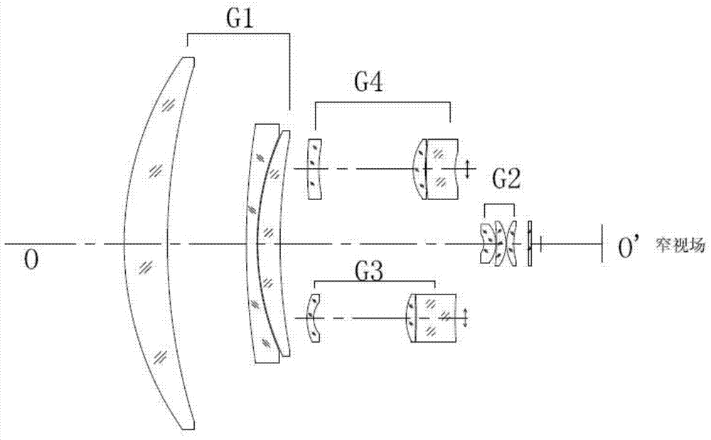
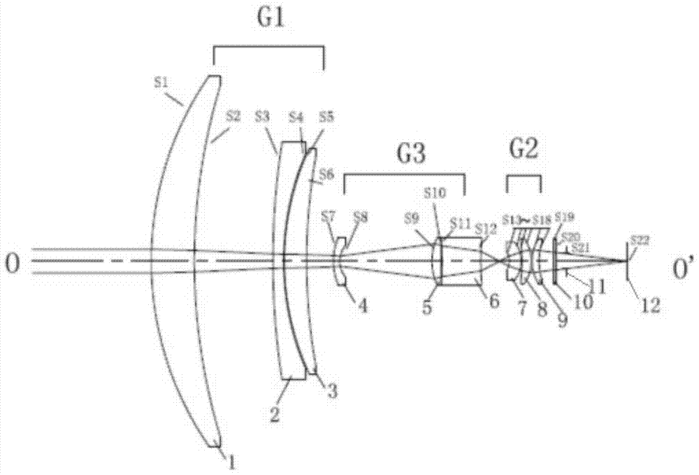
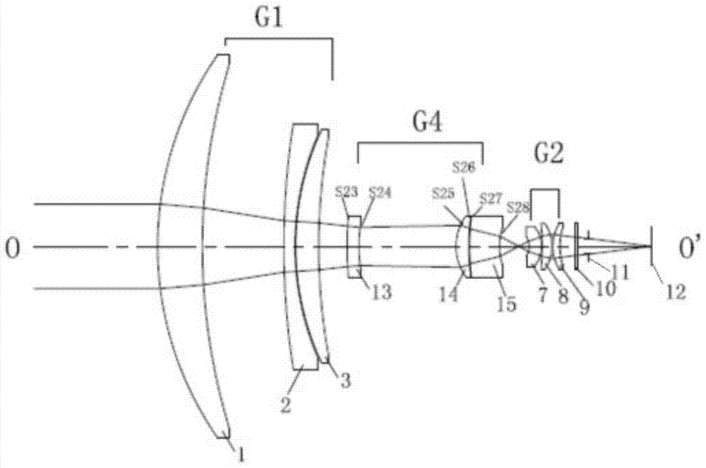
[0033] The structural schematic diagrams of the optical system of the present invention under the working conditions of large, medium and small fields of view are respectively as follows figure 2 , image 3 , Figure 4 As shown, the present invention adopts the large, medium and small three field of view switching schematic diagrams as figure 1 shown.

[0034] From the object side to the image side, there a...


PUM


Abstract

The invention discloses a compact switching type three-field-of-view mid-wave infrared optical system. The compact switching type three-field-of-view mid-wave infrared optical system includes a front lens group G1, a relaying lens group G2, a wide-field-of-view conversion lens group G3 and a middle-field-of-view conversion lens group G4 which are distributed from an object side to an image side sequentially, wherein the front lens group G1 and the relaying lens group G2 are shared by a wide-field-of-view state, a middle-field-of-view state and a narrow-field-of-view state. According to the compact switching type three-field-of-view mid-wave infrared optical system of the invention, the axial dimension of the optical system is compressed through utilizing a secondary imaging principle; and the conversion of the field of views of the optical system is realized through the radial switching in and switching out of the magnification-varying lens group G3 and the magnification-varying lens group G4. The axial dimension of the optical system is compact, and therefore, light path folding realized by additionally adopting reflecting mirrors can be avoided; and the narrow field of view of the optical system has highest optical axis precision and highest optical transmission rate; and the switching time of the fields of view of the optical system is short.

Description

technical field [0001] The invention discloses a compact switchable three-field mid-wave infrared optical system and relates to the technical field of infrared thermal imaging. Background technique [0002] The application field of infrared thermal imaging usually requires that the infrared optical system can provide high magnification small field of view images and low magnification large field of view images at the same time to complete the system's search, aiming and tracking functions for targets. Two or more zoom infrared optical systems are simple and practical. The large field of view or low magnification mode of the dual-field infrared optical system can be used to observe a large scene area and search for suspected targets. The small field of view or high magnification mode can be used to carefully Observe or zoom in on the target, identify, track and aim the target. When the focal length zoom ratio between the large field of view and the small field of view is rel...

Claims


Application Information

Patent Timeline
Patent Type & Authority Patents(China)
IPC IPC(8): G02B27/00
CPCG02B27/0075
Inventor 梁思远吴玉堂朱敏黄胜弟王善忠
Owner NANJING WAVELENGTH OPTO ELECTRONICS SCI & TECH CO LTD
Learn More