Method for designing highly uniform region magnetic field coil in magnetic shielding environment

A design method and technology of magnetic field coils, applied in computing, special data processing applications, instruments, etc., can solve problems such as inability to obtain optimal values, inability to obtain coil magnetic field analytical models, and increased calculations

Active Publication Date: 2016-03-30
BEIJING AUTOMATION CONTROL EQUIP INST
View PDF3 Cites 11 Cited by
  • Summary
  • Abstract
  • Description
  • Claims
  • Application Information

AI Technical Summary

Problems solved by technology

Since the uniform area of ​​the coil is proportional to the volume of the coil, when the structure of the coil remains unchanged and the size decreases, the uniform area of ​​the magnetic field generated by it will decrease accordingly; at the same time, if the conventional magnetic coil structure and design method are still used, the magnetic shielding boundary will be reduced. Reduce the size of the reluctance in the coil magnetic circuit, thereby changing the magnetic flux path, resulting in a significant reduction in the uniformity of the coil magnetic field
When designing high-uniformity magnetic field coils under the magnetic shielding boundary, the influence of the magnetic shielding boundary on the coil magnetic field cannot be quantitatively solved by analytical methods, and can only be simulated by finite element calculations, which makes it impossible to obtain an analytical model of the coil magnetic field, making When the coil is optimized, the amount of calculation is greatly increased, and the optimal value cannot even be obtained

Method used


Image

  • Method for designing highly uniform region magnetic field coil in magnetic shielding environment
  • Method for designing highly uniform region magnetic field coil in magnetic shielding environment
  • Method for designing highly uniform region magnetic field coil in magnetic shielding environment

Examples


Embodiment Construction

[0036] A method for designing a highly uniform magnetic field coil under a magnetic shield boundary according to the present invention will be described in detail below in conjunction with the accompanying drawings and specific embodiments.

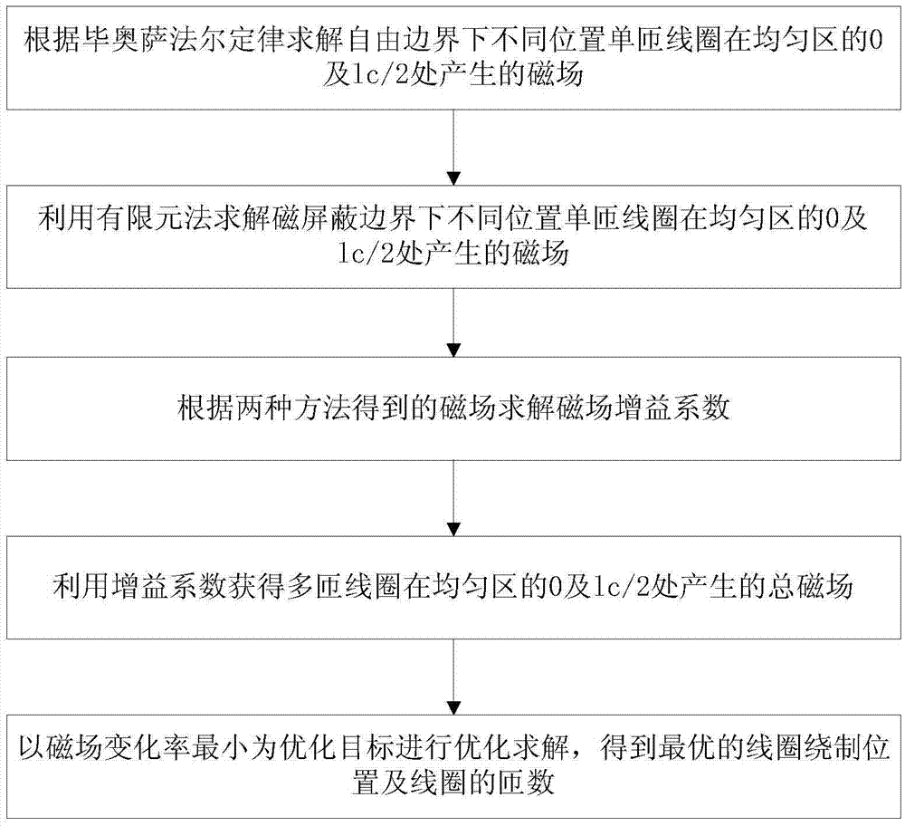
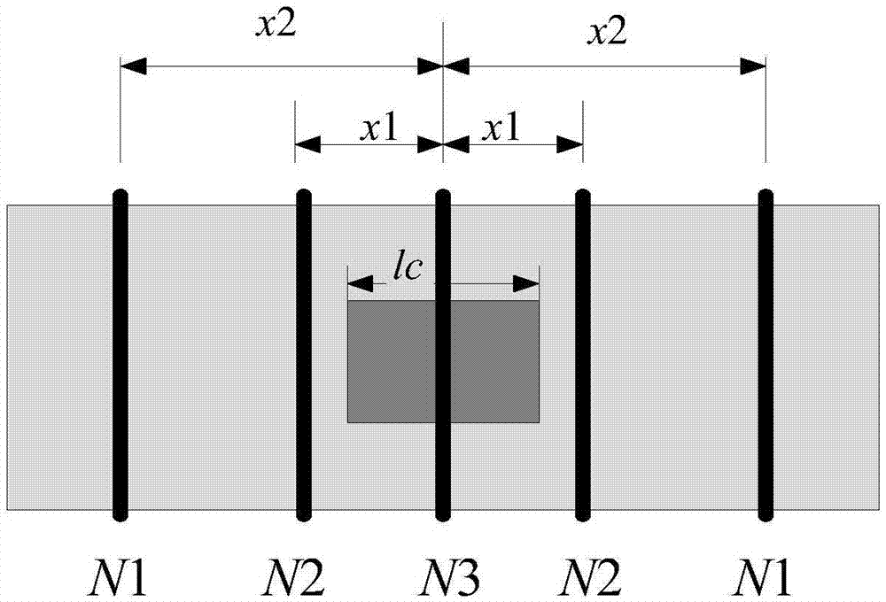
[0037] Such as figure 1 with figure 2 As shown, the present invention is a design method of a high-uniformity magnetic field coil in a magnetic shielding environment. The following uses a five-segment winding coil as an example to illustrate the present invention, but the present invention is not limited to the use of a five-segment winding coil , the invention can be used in the design of various types of coils such as cylindrical and square coils under the magnetic shielding boundary.

[0038] In the case where the size of the magnetic shielding barrel is known, when the internal coil of the magnetic shielding barrel is wound in five sections, the structural parameters of the inner coil of the magnetic shielding barrel mainly include ...


PUM


Abstract

The present invention relates to a method for designing a highly uniform magnetic field coil, in particular to a method for designing a highly uniform magnetic field coil in a magnetic shielding environment. According to the method provided by the present invention, a ratio of a magnetic field calculated by the Biot-Savart Law under a condition of a free boundary to a magnetic field calculated under a condition of establishing a magnetic shielding boundary model by a finite element method is set as an equivalent gain coefficient of amplification of a magnetic shielding boundary to a coil magnetic field coefficient; a field and circuit integrated method is adopted; and coil parameters are subjected to optimal design by using the minimum change rate of the coil magnetic field as the target. Compared with an existing coil design method under the magnetic shielding boundary, which completely adopts the finite element method to carry out design, the method disclosed by the present invention can obtain a coil structural parameter with a higher uniformity and has high computation efficiency and feasibility.

Description

technical field [0001] The invention relates to a design method for a high-uniform magnetic field coil, in particular to a design method for a high-uniform magnetic field coil under a magnetic shielding environment. Background technique [0002] The nuclear magnetic resonance gyroscope is one of the main development directions of the next generation gyroscope technology. The magnetic coil and the magnetic shielding layer are the main actuators for magnetic field control in the NMR gyroscope. The uniformity of the magnetic field generated by the magnetic coil directly affects the precision control capability of the nuclear spin ensemble, and is one of the core factors that determine the accuracy of the gyroscope. With the reduction of the size of the nuclear magnetic resonance gyroscope, the components such as the magnetic shielding layer and the magnetic field coil are also reduced. Waste of space. Since the uniform area of ​​the coil is proportional to the volume of the c...

Claims


Application Information

Patent Timeline
Patent Type & Authority Applications(China)
IPC IPC(8): G06F17/50
Inventor 郑辛王春娥秦杰汪世林高溥泽
Owner BEIJING AUTOMATION CONTROL EQUIP INST
Why Eureka
Try Eureka