A method for controlling the environment of a chamber

A control method and chamber technology, which are used in semiconductor/solid-state device manufacturing, discharge tubes, electrical components, etc., can solve the problems of poor process stability and repeatability, corrosion of the inner surface of the chamber, and low equipment utilization, and improve the use of Longevity and utilization, guaranteed stability and repeatability, effect of extended cleaning intervals

Active Publication Date: 2017-10-24
BEIJING NAURA MICROELECTRONICS EQUIP CO LTD
View PDF3 Cites 0 Cited by
  • Summary
  • Abstract
  • Description
  • Claims
  • Application Information

AI Technical Summary

Problems solved by technology

[0005] In practical application, the above method inevitably has the following problems: because the deposited fluoropolymer will interact with the Al on the inner surface of the chamber 2 o 3 Happened Al 2 o 3 +F→AlF 3 ↓+O 2 reaction, wherein, AlFx is a fluorine-containing deposit that is difficult to volatilize and is not easy to remove. Therefore, the following problems will exist in the above method: (1) cause corrosion to the inner surface of the chamber, thereby reducing the service life of the equipment; (2) corrosion produced The gradual accumulation of fluorine-containing deposits will easily peel off from the inner surface of the chamber, thereby polluting or affecting the process; (3) The fluorine-containing deposits produced by corrosion will have a fluorine memory effect, and the fluorine will be released in the next process to affect the chamber environment. impact, resulting in process drift, resulting in poor process stability and repeatability; (4) The fluorine-containing deposits produced by corrosion will shorten the cleaning time interval of the chamber, resulting in low equipment utilization

Method used


Image

  • A method for controlling the environment of a chamber
  • A method for controlling the environment of a chamber
  • A method for controlling the environment of a chamber

Examples


Embodiment Construction

[0030] In order for those skilled in the art to better understand the technical solutions of the present invention, the method for controlling the chamber environment provided by the embodiments of the present invention will be described in detail below with reference to the accompanying drawings.

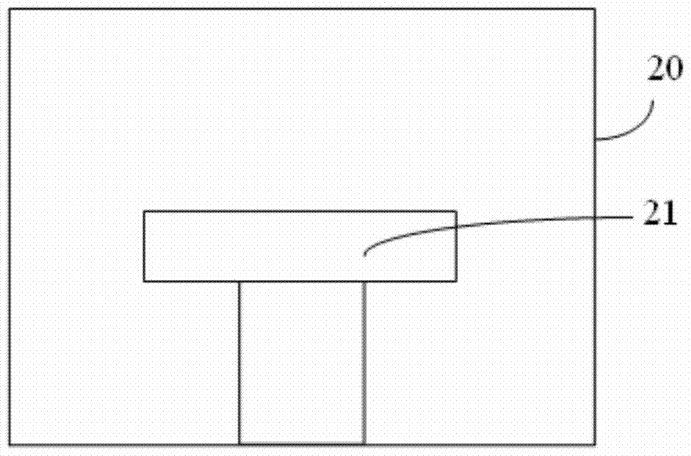
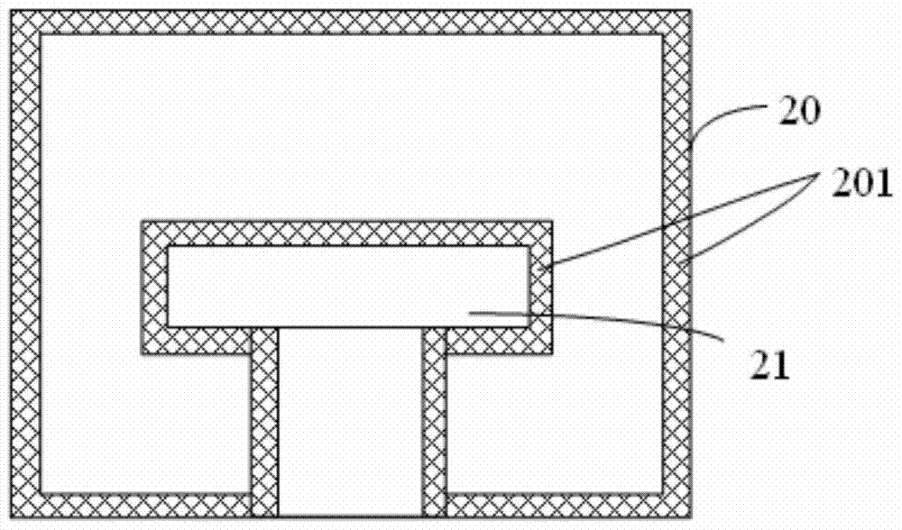
[0031] To facilitate the understanding of the present invention, the "inner surface of the chamber" mentioned in the present application refers to the surface exposed to the environment of the chamber.

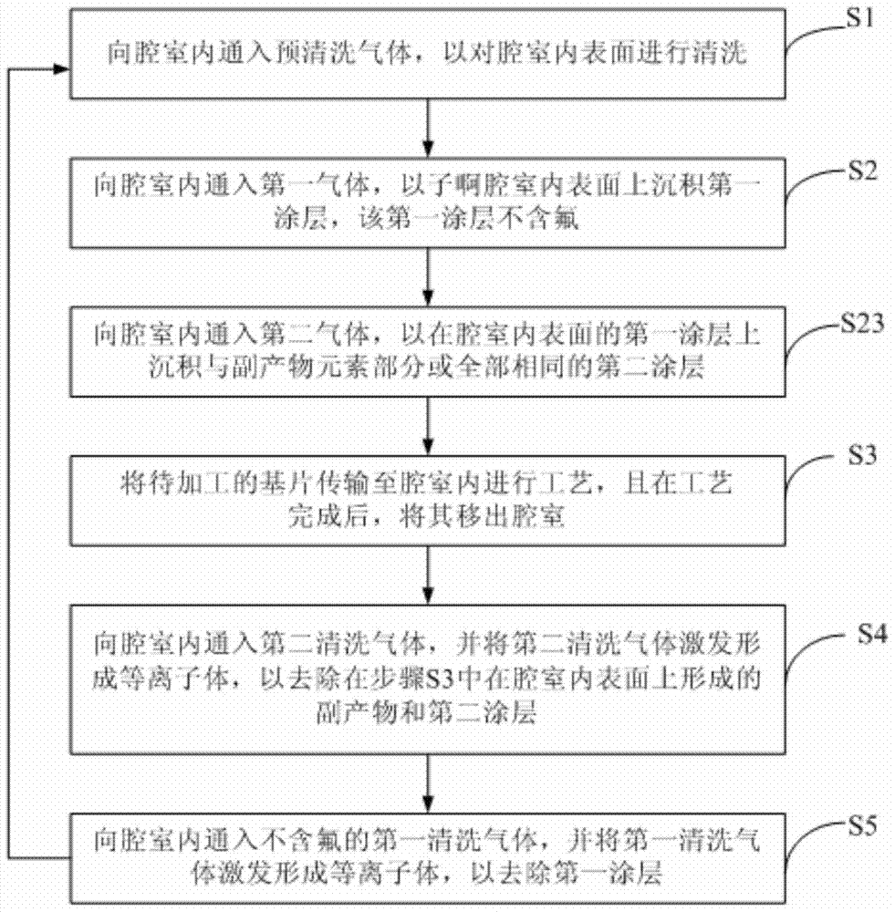
[0032] figure 1 It is a flowchart of a method for controlling a chamber environment provided by an embodiment of the present invention. see figure 1 , the control method of the chamber environment provided in this embodiment includes the following steps:

[0033] Step S1, injecting pre-cleaning gas into the chamber to clean the inner surface of the chamber so that the chamber is a clean chamber;

[0034] Step S2, introducing a first gas into the chamber to deposit a first coatin...


PUM


Abstract

The invention provides a chamber environment control method comprising the following steps: step S1, feeding a pre-cleaning gas into a chamber to clean the inner surface of the chamber; step S2, feeding a first gas into the chamber to deposit a first coating on the inner surface of the chamber, wherein the first coating does not contain fluorine; step S3, transmitting a to-be-processed substrate into the chamber for a process, and removing the to-be-processed substrate out of the chamber after the process is completed; step S4, feeding a second cleaning gas into the chamber, and exciting the second cleaning gas to form a plasma so as to remove byproducts formed on the inner surface of the chamber in step S3; and step S5, feeding a first cleaning gas containing no fluoride into the chamber, and exciting the first cleaning gas to form a plasma so as to remove the first coating and restore the chamber environment. The method can avoid the corrosion of fluoride to the inner surface of the chamber and fundamentally eliminate the fluorine memory effect of the chamber, and therefore, the chamber environment is consistent for each process.

Description

technical field [0001] The invention belongs to the technical field of microelectronic processing, and in particular relates to a method for controlling the environment of a chamber. Background technique [0002] With the development of technology, the feature size of integrated circuits is continuously shrinking, which makes the requirements for semiconductor processes more and more stringent, especially for photolithography and silicon etching processes. In practical applications, the silicon etching process mainly uses plasma etching, and the chamber environment where the plasma is located is one of the important factors affecting the stability and repeatability of the etching process. [0003] Specifically, after an etching process is completed, by-products (for example, fluorine-containing and carbon-containing by-products) will be deposited on the inner surface of the chamber, and the by-products will have an impact on the chamber environment, which will affect the nex...

Claims


Application Information

Patent Timeline
Patent Type & Authority Patents(China)
IPC IPC(8): H01J37/32H01L21/67
Inventor 陈永远
Owner BEIJING NAURA MICROELECTRONICS EQUIP CO LTD
Why Eureka
Try Eureka