A UPS current equalization control system

A flow control system and flow control technology, applied in the direction of emergency power supply arrangements, electrical components, circuit devices, etc., can solve problems such as the inability to solve the current sharing problem of multiple UPS modules, achieve the adjustment process, improve adjustment accuracy, and simplify fine-tuning The effect of the process

Active Publication Date: 2019-01-22
EMERSON NETWORK POWER CO LTD
View PDF0 Cites 0 Cited by
  • Summary
  • Abstract
  • Description
  • Claims
  • Application Information

AI Technical Summary

Problems solved by technology

[0005] The technical problem to be solved by the present invention is to provide a UPS current sharing control system, which can not only solve the problem of multiple UPS modules under full load, but also to solve the problem of current sharing of multiple UPS modules under non-full load conditions. It can also solve the current sharing problem of multiple UPS modules under non-full load conditions, such as light load or overload conditions.

Method used


Image

  • A UPS current equalization control system
  • A UPS current equalization control system
  • A UPS current equalization control system

Examples


Embodiment Construction

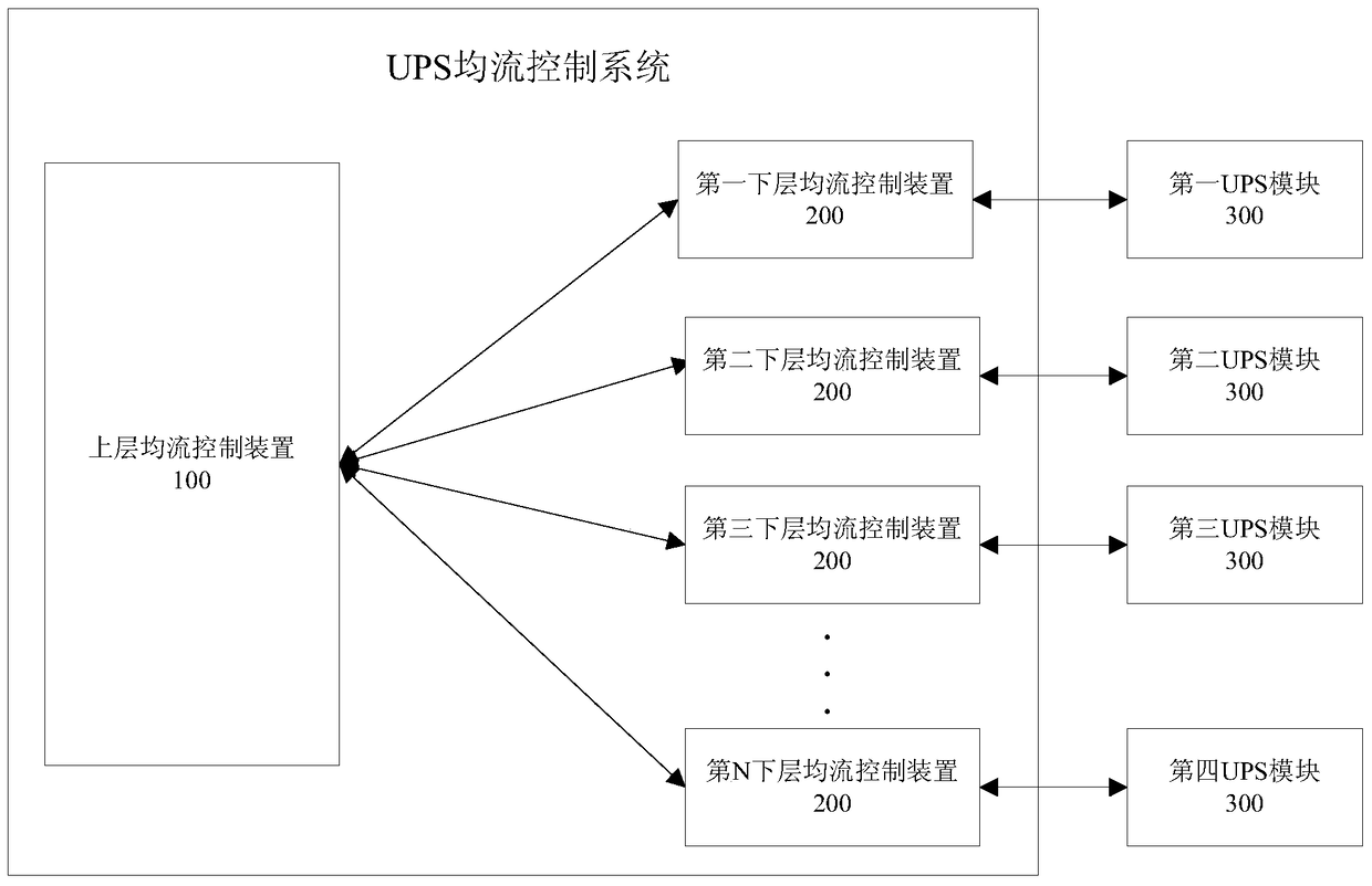
[0041] figure 1 It is a functional block diagram of the first embodiment of the UPS current sharing control system of the present invention. Such as figure 1 As shown, the UPS current sharing control system of the present invention includes: an upper layer current sharing control device 100 and a first-Nth lower layer current sharing control device 200 . The first-Nth lower layer current sharing control devices correspond to the first-Nth UPS modules 300 respectively. Those skilled in the art know that the UPS current sharing control system of the present invention may include at least two lower layer current sharing control devices 200 and UPS modules 300 respectively, that is, N≥2. Of course, in some embodiments of the present invention, the lower-level current sharing control device 200 and the UPS module 300 do not need to correspond one-to-one, and it is also possible that one or several lower-level current sharing control devices 200 realize the control of one or more ...


PUM


Abstract

The invention relates to a UPS current-equalizing control system comprising an upper current-equalizing control device and lower current-equalizing control devices. The upper current-equalizing control device is used for generating a sampling signal for controlling the sampling of various UPS modules and a switching tube driving signal for controlling the current equalization of the UPS modules. The lower current-equalizing control devices are used for sampling the sampling current of the UPS modules on the basis of the sampling signal, and enabling the current in the UPS modules to be equalized on the basis of the switching tube driving signal. The upper current-equalizing control device generates the switching tube driving signal on the basis of the sampling current. The UPS current-equalizing control system, by means of a double-layer current-equalizing control system formed by the upper current-equalizing control device and the lower current-equalizing control devices arranged in the various UPS modules, is capable of monitoring the sampling current of each UPS module in real time so as to solve a current-equalizing problem of multiple UPS modules in full-load and non-full load states, especially in a light-load or over-load state.

Description

technical field [0001] The present invention relates to an uninterruptible power supply (Uninterruptible Power System, UPS), and more specifically, to a UPS current sharing control system. Background technique [0002] For a multi-module UPS, the drive signal of the switching tube (IGBT or MOSFET, etc.) in each module is output by a controller. The controller can choose an embedded control system composed of DSP or FPGA. When the driving signal reaches each switch tube, due to the differences in the hardware drive circuit, the internal structure of the switch tube, the device difference in the power circuit and other factors, the switching time of the switch tube is different, which eventually leads to the input current or output of each module. Current inconsistencies, for example, when a 4-module UPS is running at full load, not every module is 25% loaded. During overload operation, because the load of the module greatly exceeds the design range, the final result will ca...

Claims


Application Information

Patent Timeline
Patent Type & Authority Patents(China)
IPC IPC(8): H02J9/06
Inventor 黄金金周原郑书路
Owner EMERSON NETWORK POWER CO LTD
Why Eureka
Try Eureka