Supercharge Your Innovation With Domain-Expert AI Agents!

Thermal Conduction To A Cylindrical Shaft

A cylindrical shell, thermal contact technology, applied in the field of tank system, can solve the problem of large downtime and so on

Active Publication Date: 2016-03-30
SMART EMBEDDED COMPUTING INC
View PDF3 Cites 0 Cited by
  • Summary
  • Abstract
  • Description
  • Claims
  • Application Information

AI Technical Summary

Problems solved by technology

[0006] However, to enhance the reliability of control and / or monitoring electronics in such extreme pressure and temperature environments, it is necessary to provide a protective enclosure that can avoid adverse environmental effects such as pressure or overheating, and further provide Safe and secure housing and connection methods to minimize the need for maintenance and / or replacement, which can result in significant downtime

Method used

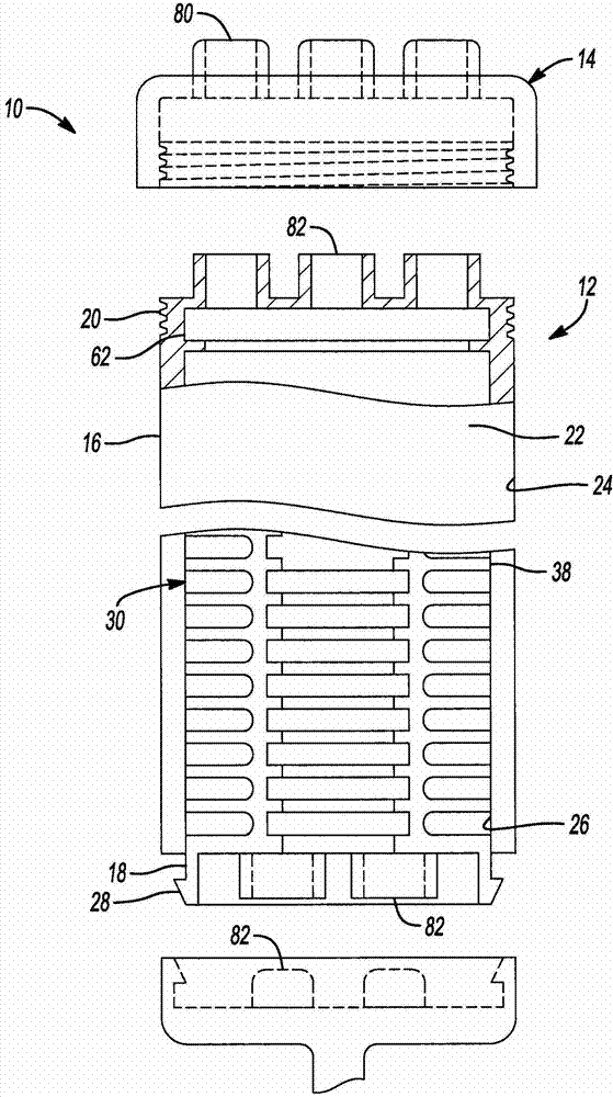
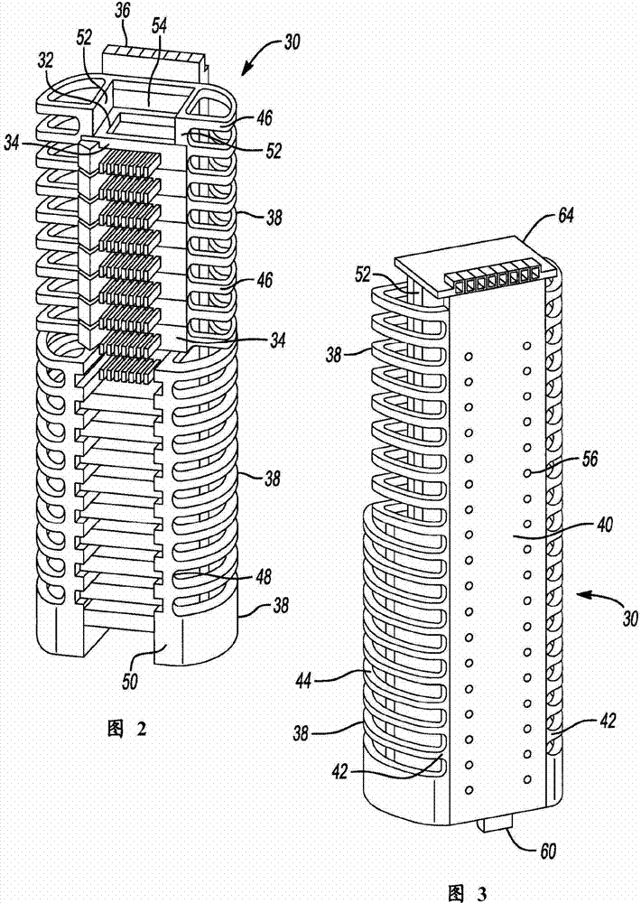
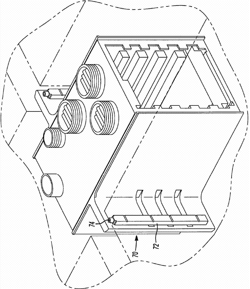

Image

  • Thermal Conduction To A Cylindrical Shaft
  • Thermal Conduction To A Cylindrical Shaft
  • Thermal Conduction To A Cylindrical Shaft

Examples


Embodiment Construction

[0017] Exemplary embodiments will now be described more fully with reference to the accompanying drawings.

[0018] Example embodiments are provided so that this disclosure will be thorough, and will fully convey the scope of the disclosure to those skilled in the art. Numerous specific details are set forth, such as examples of specific components, devices and methods, in order to provide a thorough understanding of the embodiments of the present disclosure. It will be apparent to those skilled in the art that specific details need not be employed, that example embodiments may be embodied in many different forms and that neither should be construed to limit the scope of the disclosure. In some example embodiments, well-known processes, known device structures, and well-known technologies are not described in detail.

[0019] The terminology used herein is for the purpose of describing particular exemplary embodiments only and is not intended to be limiting. As used herein, ...


PUM


Abstract

The invention relates to thermal conduction to a cylindrical shaft and a canister system. The canister system having a cylindrical housing and a modular electronic rack system disposed within the cylindrical housing. The modular electronic rack system includes a thermal contact member that is in at least selective physical contact with an interior surface of the cylindrical housing to permit conductive heat transfer there through. An input / output device extends along at least a portion of the modular electronic rack system and includes a power input and a signal output electrically coupled thereto. A plurality of electronic slots disposed at a position generally along the modular electronic rack system is provided.

Description

technical field [0001] The present disclosure relates to a tank system, and more particularly to a heat transfer system for use in a tank system. Background technique [0002] This section provides background information related to the present disclosure which is not necessarily prior art. [0003] Deep sea operations are an important part of many industries today. This is especially true in the oil and gas industry. As global energy demand grows and onshore oil and gas reserves dwindle, there is a new need to produce oil and gas from offshore locations. In fact, in 2007, more than one-third of all oil produced was pumped from offshore locations. As shale production advances, the location of these oil production rigs is moving into deeper waters. [0004] In the past, much of the equipment used in oil and gas production was located above water on specially designed rigs. However, with the advancement of deepwater equipment, many of the required pumps, compressors and ag...

Claims


Application Information

Patent Timeline
Patent Type & Authority Applications(China)
IPC IPC(8): H05K5/02H05K5/06
CPCH05K7/2039H05K7/1434H05K7/14337H05K1/0203H05K1/181H05K1/0201H05K7/20445H05K7/1427H05K2201/066H05K7/026H05K1/0204H05K7/20409H05K5/0247H05K7/023H05K7/20H05K7/2049H05K7/20418H05K7/20427H05K7/20436G06F1/183G06F1/20G06F1/188
Inventor 马丁·彼得·约翰·科尔内斯苏珊娜·马里耶·翁罗丝·L·阿姆斯壮道格拉斯·L·桑迪
Owner SMART EMBEDDED COMPUTING INC
Features
  • R&D
  • Intellectual Property
  • Life Sciences
  • Materials
  • Tech Scout
  • Unparalleled Data Quality
  • Higher Quality Content
  • 60% Fewer Hallucinations
Learn More