
Space aircraft

A space vehicle and aircraft technology, applied in the direction of aircraft, aerospace vehicles, space vehicle propulsion system devices, etc., can solve the problems of space vehicle flight deceleration, air inlet resistance, etc.

Inactive Publication Date: 2016-03-30
AIRBUS DEFENCE & SPACE
View PDF4 Cites 0 Cited by
  • Summary
  • Abstract
  • Description
  • Claims
  • Application Information

AI Technical Summary

Problems solved by technology

During this phase of flight, the air inlets of the aerobic propulsion units thus create significant resistance, which slows down the flight of the spacecraft

Method used


Image

  • Space aircraft
  • Space aircraft
  • Space aircraft

Examples


Embodiment Construction

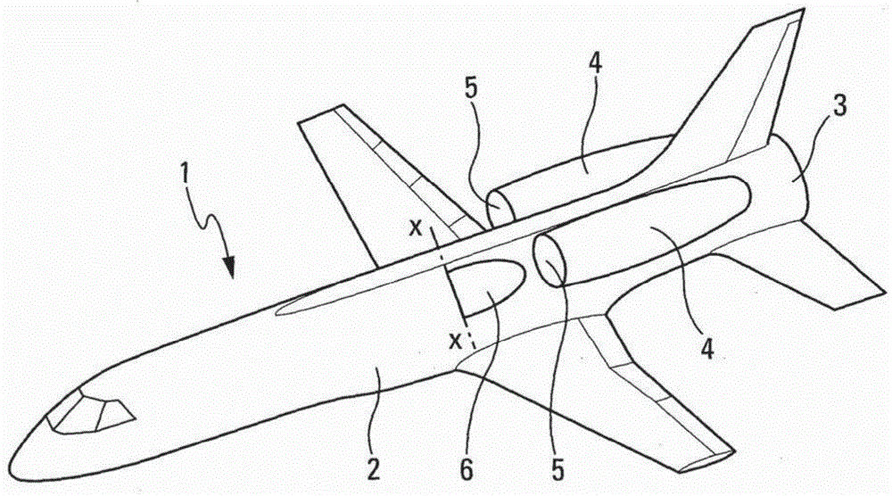
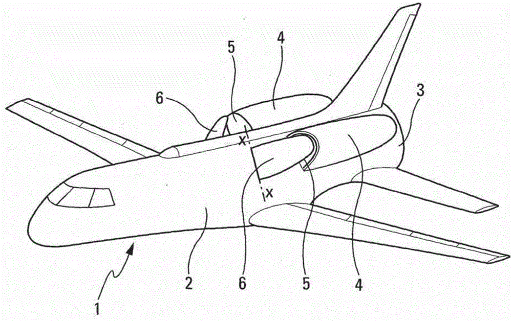
[0016] According to the present invention and in figure 1 with figure 2 The space vehicle 1 shown in FIG. 2 comprises only one stage with a fuselage 2 and is capable of transonic and / or supersonic flight.

[0017] Said space vehicle 1 comprises at least one rocket engine 3 and two turboshaft engines 4 each comprising an air inlet 5 . The turboshaft engines are arranged laterally at the rear of the fuselage 2 such that one of the turboshaft engines 4 is located on the left side of the fuselage 2 and the other of said turboshaft engines 4 is located on the right side of the fuselage 2 .

[0018] The air inlet 5 is an important source of aerodynamic drag when the spacecraft is flying at transonic or supersonic speeds and the turboshaft engine 4 is not operating.

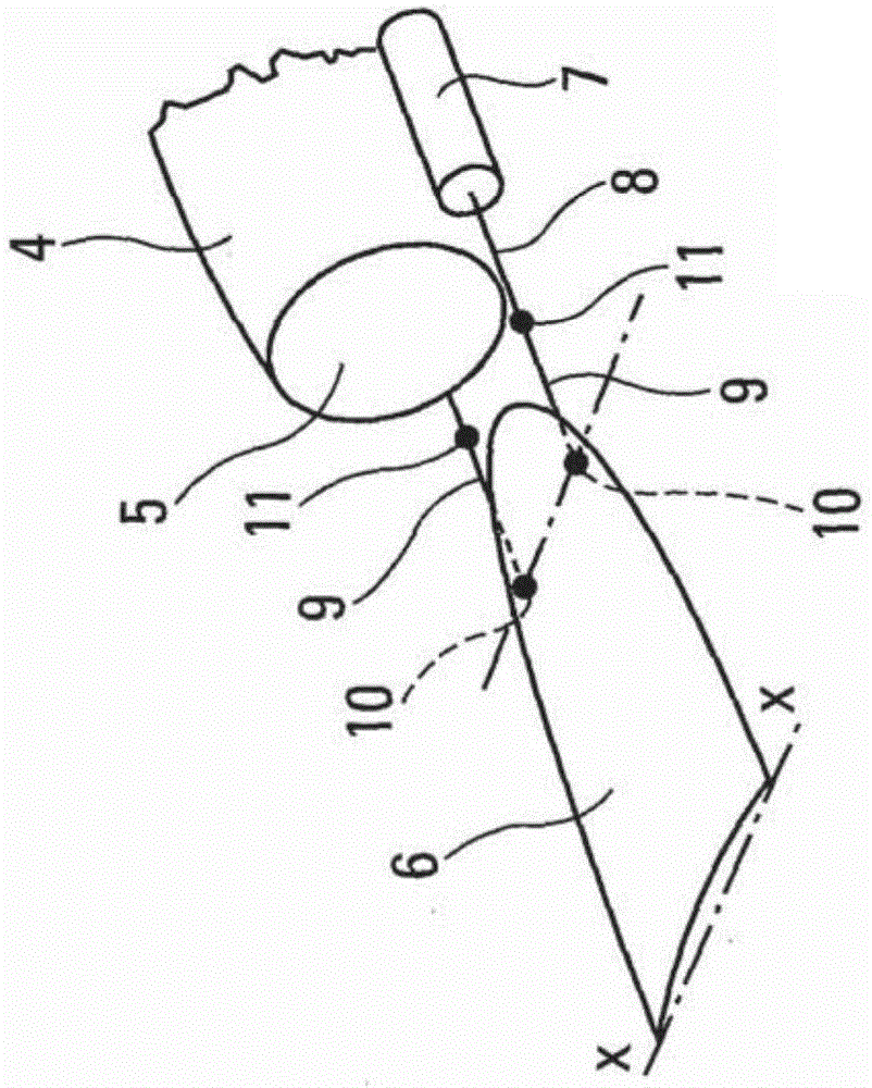
[0019] Therefore, to compensate for this shortcoming, figure 1 with figure 2 In front of each of the two air inlets 5 , the spacecraft 1 comprises a rotating flap 6 articulated about the axis X-X of the frame of t...


PUM


Abstract

- According to the invention, said space aircraft comprises, at the front of each of the air inlets (5) of the turbo engines (4), a mobile flap (6) that can move, in both directions, between a first position for which said flap opens said air inlet (5) and a second position for which said flap prevents air from entering said air inlet (5).

Description

technical field [0001] The present invention relates to a space vehicle capable of taking off from the ground in the usual way, capable of reaching an altitude of at least one hundred kilometers at transonic or even supersonic speeds, and then also capable of landing. Background technique [0002] Such single-stage space vehicles capable of flying at speeds greater than Mach 0.9 include anaerobic propulsion means such as rocket engines and aerobic propulsion means such as turboshaft engines. [0003] During the flight of such a space vehicle, only the anaerobic propulsion means may be operated, while the aerobic propulsion means are inactive or switched off. During this phase of flight, the air inlets of the aerobic propulsion units thus create a high drag, which slows down the flight of the spacecraft. [0004] The aim of the present invention is to remedy this disadvantage. Contents of the invention [0005] To this end, the present invention provides a single-stage s...

Claims


Application Information

Patent Timeline
IPC IPC(8): B64D33/02B64C30/00B64G1/00B64G1/14B64G1/40F02K7/18
CPCB64D33/02B64G1/14B64D2033/026F02C7/042F02C7/05B64D2033/0253B64G1/4005B64G1/40
Inventor 欧金尼奥·费雷拉马尔科·普兰波利尼约翰·科拉伯夫
Owner AIRBUS DEFENCE & SPACE
Learn More