Gear inner ring interference fit tool clamp

A technology of interference fit and tooling fixtures, which is applied in gear tooth manufacturing devices, manufacturing tools, belts/chains/gears, etc., can solve the problems of low gear machining accuracy and non-common central axis, etc., and achieve simple structure and high reliability , a wide range of effects

Inactive Publication Date: 2016-04-06
CHONGQING SHUNHUAI MACHINERY MFG CO LTD
View PDF1 Cites 3 Cited by
  • Summary
  • Abstract
  • Description
  • Claims
  • Application Information

AI Technical Summary

Problems solved by technology

[0007] The present invention intends to provide an interference fit fixture for the inner ring of the gear, so as to solve the problems in the prior art that the inner

Method used


Image

  • Gear inner ring interference fit tool clamp
  • Gear inner ring interference fit tool clamp

Examples


Embodiment Construction

[0016] The present invention will be described in further detail below by means of specific embodiments:

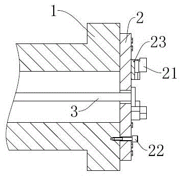
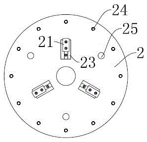
[0017] The reference signs in the accompanying drawings of the specification include: the rotating shaft seat 1 , the chuck 2 , the jaw 21 , the pin 22 , the T-shaped slot 23 , the connection hole 24 , the pin hole 25 , and the piston rod 3 .

[0018] The embodiment is basically as attached figure 2 As shown: there are twelve connecting holes 24 evenly distributed on the outermost circle of the outer circumference of the chuck 2, and three T-shaped chute 23 are evenly distributed on the chuck 2 with the center of the chuck 2 as the center, and the T-shaped chute 23 is fixed on the chuck 2 through the inner hexagonal bolt, and a T-shaped slider matching the T-shaped groove 23 is arranged in the T-shaped groove 23, and on the T-shaped slider, the T-shaped slider passes through two inner hexagons. The fixed clamping jaws 21 are connected by bolts, pin holes 25 are provided...


PUM


Abstract

The invention discloses a gear inner ring interference fit tool clamp. The clamp comprises a rotating shaft seat, a chuck and a pull rod. The chuck and the rotating shaft seat are coaxially and rotatably connected, and three clamping jaws are evenly distributed on the circumference of the chuck; the outer circumferential faces of the clamping jaws are in interference fit with the inner ring of a machined gear, and the pull rod pushes and pulls the center of the chuck to move in the axial direction of the centre of the chuck; and positioning blocks are arranged on the sides of the clamping jaws of the chuck. According to the gear inner ring interference fit tool clamp, the problems that in the prior art, a gear penetrates a mandrel, so that the gear inner ring and the mandrel do not share the central axis, and the gear machining precision is low are solved.

Description

technical field [0001] The invention relates to a fixture for fixing a ring gear, in particular to an interference fit fixture for a gear inner ring. Background technique [0002] The fixture is a device used to fix the processing object in the machining process so that it occupies the correct position to accept construction or inspection. In a broad sense, any process in the process, the device used to install the workpiece quickly, conveniently and safely, can be a fixture. [0003] The accuracy of the initial processing fixture will be relatively low, and the positioning accuracy of the high-precision fixture will be higher. [0004] In the patent document with the patent number 201410690466.9, a gripper fixture for the finishing of this wheel is disclosed, which includes a fixture head, the left end of the fixture head is a disc fixed base with cylindrical bosses arranged on both sides, and the right end is a threaded Cylindrical main shaft, a disc-shaped backing plate...

Claims


Application Information

Patent Timeline
IPC IPC(8): B23F23/06
CPCB23F23/06
Inventor 王建权
Owner CHONGQING SHUNHUAI MACHINERY MFG CO LTD
Why Eureka
Try Eureka