Vibration grinding method and device

A grinding method and technology of a grinding device, which are applied to grinding machines, grinding/polishing equipment, and machine tools suitable for grinding the edge of workpieces, etc., which can solve the problems of inconvenient discharging of parts, complex structure of grinding machines, and unfavorable large-scale production, etc. problems, to achieve the effect of convenient discharge, diversified functions and uses, and conducive to large-scale production

Inactive Publication Date: 2016-04-06
湖州中云机械制造股份有限公司
View PDF8 Cites 3 Cited by
  • Summary
  • Abstract
  • Description
  • Claims
  • Application Information

AI Technical Summary

Problems solved by technology

[0002] When the existing grinder is grinding, when the grinding is completed and the material needs to be discharged, it is necessary to manually install the discharge sorting device to the discharge port, and then Carrying out material sorting, which leads to the inconvenience of discharging the parts after grinding; moreover, the parts often need to be cleaned and rust-proofed after being ground and discharged, but the existing treatment methods are first Use a grinder to grind the parts, and after grinding and discharge, use other corresponding tools to clean and rust the parts. This process not only needs to use a lot of machinery and equipment, but also consumes time and labor, which affects work efficiency. It is conducive to large-scale production; at the same time, the existing grinding is all grinding in the same direction, resulting in unsatisfactory grinding effect; in addition, the structure of the existing grinding machine is also very complicated
Therefore, the existing vibrating grinder has problems such as inconvenient discharge, single function, poor grinding effect, low work efficiency, unfavorable for large-scale production and complex structure.

Method used


Image

  • Vibration grinding method and device
  • Vibration grinding method and device
  • Vibration grinding method and device

Examples


Embodiment 1

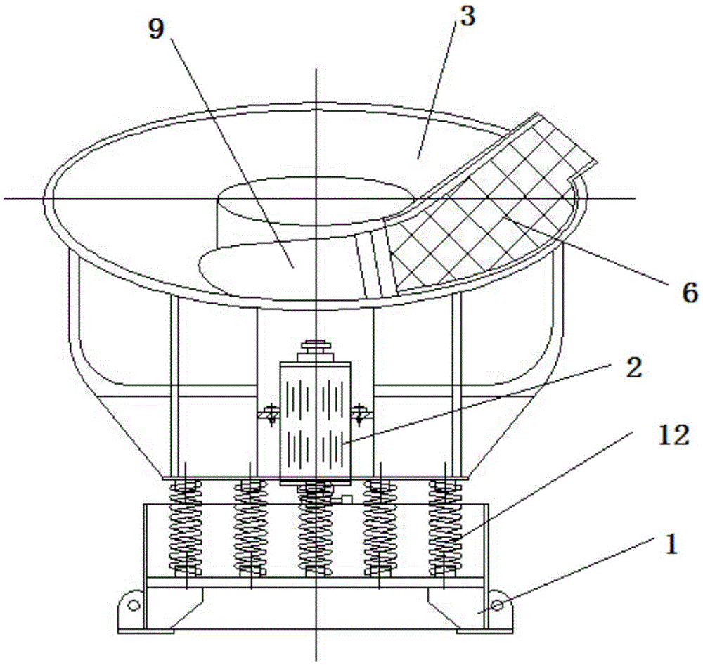
[0022] Example 1. The structure of the single groove vibration grinding machine is as follows: figure 1 As shown, including a base 1, a vibrating motor 2 is provided above the base 1, an annular grinding tank 3 with a flat groove structure is provided above the vibrating motor 2, a first screen plate 6 is provided at the outlet of the grinding tank 3, and the first screen plate 6 is connected with a first discharge plate 9; the first discharge plate 9 is a swing structure, and one end of the first discharge plate 9 is in contact with the bottom of the grinding tank 3, and the other end is connected with the first screen plate 6. Its working principle: Grind and discharge the parts through the vibration motor 2, the annular grinding tank 3 and the first discharge plate 9 that can swing up and down at one end; put the parts to be ground into the grinding tank 3 loaded with abrasives, and control The rotation direction of the vibrating motor 2 is the same as that of the disch...

Embodiment 2

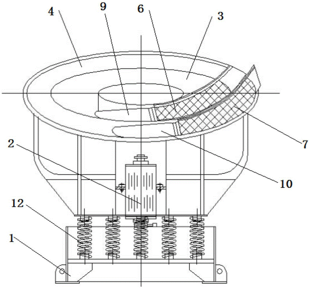
[0023] Example 2. Double groove vibrating grinder, constituted as figure 2 As shown, an annular cleaning tank 4 with a flat groove structure is provided on the outer ring of the grinding tank 3 of the single-trough vibration grinder, and a second screen plate 7 is provided at the outlet of the cleaning tank 4, and the second screen plate 7 is connected with a second The discharge plate 10 and the second discharge plate 10 are of swing structure, and one end of the second discharge plate 10 is in contact with the bottom of the cleaning tank 4 , and the other end is connected with the second screen plate 7 . Its working principle: after the parts come out of the grinding tank 3 in embodiment 1, they enter the cleaning tank 4, and the rotation direction of the vibration motor 2 is controlled to be the same as that of the discharge port. The parts and cleaning liquid flow from the bottom of the second discharge plate 10, forcing the first The second discharge plate 10 swings u...

Embodiment 3

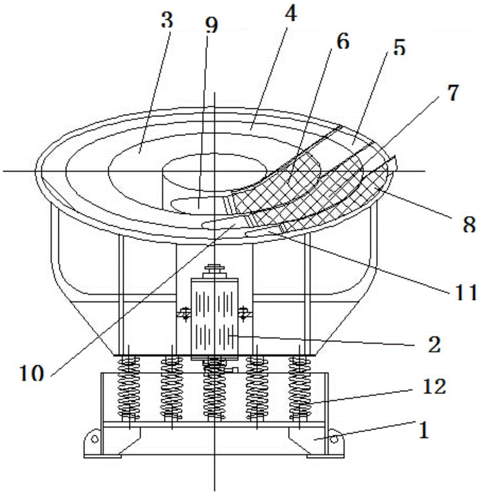
[0024] Example 3. Three-slot vibration grinder, constituted as image 3 As shown, the outer ring of the cleaning tank 4 of the double-groove vibration grinder is provided with an annular anti-rust sinking tank 5 with a flat tank structure, and a third screen plate 8 is arranged above the anti-rust sinking tank 5, and the third screen plate 8 is connected with a third discharge plate 11, the third discharge plate 11 is a swing structure, and one end of the third discharge plate 11 is in contact with the bottom of the anti-rust sinking tank 5, and the other end is connected with the third screen plate 8. Its working principle: After being cleaned by the cleaning tank 4 in embodiment 2, the parts enter the anti-rust sinking tank 5 provided on the outer ring of the cleaning tank 4, and the cleaned parts enter the anti-rust sinking tank to control the rotation direction of the vibration motor In the same direction as the discharge port, the parts flow from the bottom of the thir...


PUM


Abstract

The invention discloses a vibration grinding method and device. A vibration motor is matched with a discharging plate to use, the motion direction of a part in an annular slot is changed through changing the rotating direction of the vibration motor, the position of the discharging plate is controlled through changing the motion direction of the part, and furthermore the part is controlled to be switched between a working state and a discharging state. The vibration grinding device comprises a base (1), wherein the vibration motor (2) is arranged above the base (1); a grinding slot (3) with an annular flat slot structure is arranged above the vibration motor (2); a first screen plate (6) is arranged at an outlet of the grinding slot (3) and is connected with a first discharging plate (9); and the first discharging plate (9) is of a swing-type structure, one end of the first discharging plate (9) is in contact with the bottom of the grinding slot (3), and the other end of the first discharging plate (9) is connected with the first screen plate (6). The vibration grinding device has the characteristics of convenience in discharge, good grinding effect, functional diversity, high work efficiency, large-scale production advantage and simple structure.

Description

technical field [0001] The invention relates to a grinding method and device, in particular to a vibration grinding method and device. Background technique [0002] When the existing grinding machine is grinding, when the grinding is completed and the material needs to be discharged, it is necessary to manually install the discharging and sorting device to the discharge port, and then carry out the discharging and sorting, resulting in the parts after grinding It is inconvenient to discharge the material; moreover, the parts often need to be cleaned and rust-proofed after being ground and discharged, but the existing treatment method is to grind the parts with a grinder first, and then use another Corresponding tools are used to clean and rust-proof the parts. This process not only requires the use of a large number of machinery and equipment, but also consumes time and labor, affects work efficiency, and is not conducive to large-scale production; direction grinding, resul...

Claims


Application Information

Patent Timeline
Patent Type & Authority Applications(China)
IPC IPC(8): B24B31/073B24B31/16B24B31/12
CPCB24B31/073B24B31/12B24B31/16
Inventor 罗中云罗金丽
Owner 湖州中云机械制造股份有限公司
Why Eureka
Try Eureka