A tool for automatic cable ties in narrow spaces

A small space, automatic technology, applied in the direction of bundling materials, paper/cardboard containers, containers, etc., can solve the problems such as the inability to realize automation of lagging and cable ties, and the inability to realize motor coils.

Active Publication Date: 2019-11-22
SHENZHEN SWIFT AUTOMATION TECH CO LTD
View PDF5 Cites 0 Cited by
  • Summary
  • Abstract
  • Description
  • Claims
  • Application Information

AI Technical Summary

Problems solved by technology

[0003] The purpose of the present invention is to solve the problem that the existing various automatic cable tie equipment and tools on the market cannot realize the automatic cable tie operation in such a narrow space as the motor coil, and develop a brand new automatic cable tie method and tool. So far, other processes of motor production can be automated, only coil wrapping and cable ties cannot be automated. Coil wrapping and cable ties are the bottleneck of motor automation production. automatic tie tool

Method used


Image

  • A tool for automatic cable ties in narrow spaces
  • A tool for automatic cable ties in narrow spaces
  • A tool for automatic cable ties in narrow spaces

Examples


Embodiment 1

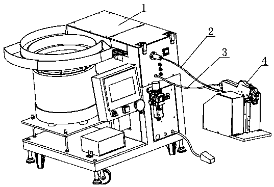
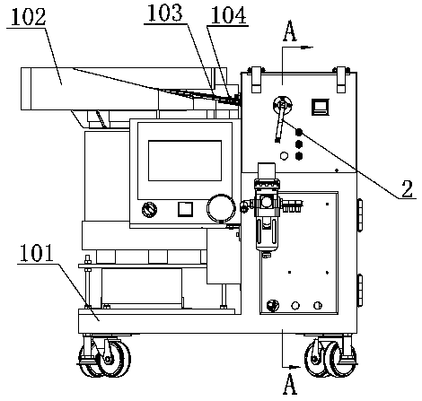
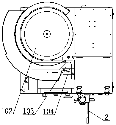
[0059] Such as figure 1 , figure 2 , image 3 , Figure 4 , Figure 5 , Figure 6 , Figure 7 , oneA method and tool for automatic cable ties in a narrow space, including a host 1, a feeding tube 2, a data line 3, and an automatic cable tie working head 4, the host 1 communicates with the automatic cable tie through the feeding tube 2 and the data line 3 Connected with working head 4, the host 1 includes: host frame 101, vibrating plate 102, direct vibrator 103, direct vibrating plate 104, pusher cylinder 105, pusher block 106, cable tie sensor 107, pusher body 108, the feeding pipe connector 109, the valve 110, the valve cylinder 111, the electrical control system 112 and the air valve 113 are installed on the main frame 101, the direct vibrating plate 104 is fixed above the direct vibrating device 103, and the There is a groove on the straight vibrating plate 104 for the movement and guidance of the head of the cable tie. One end of the straight vibrating plate 104 ...

Embodiment 2

[0061] Such as Figure 8 , Figure 9 , Figure 10 , Figure 11 , Figure 12 , Figure 13 As shown, the automatic cable tie working head 4 includes an automatic cable tie working head body 41, a piercing and cutting combination module 42, a fixed second guide claw 42156, a movable second guide claw 42157, a movable second guide claw Claw cylinder 43, lifting cylinder 44, lifting cylinder 45, lifting slider 46, the fixed second guide claw 42156, movable second guide claw cylinder 43, lifting cylinder 45 are fixed on the automatic cable tie working head body 41, the movable second guide claw 42157 is connected with the action rod of the movable second guide claw cylinder 43 and can slide in the guide groove of the automatic cable tie working head body 41, the lifting Cylinder 45 is fixed on the working head body 41 of the automatic cable tie, and the lifting cylinder 44 is fixed on the lifting slider 46. The piercing, drawing and cutting combination module 42 is connected, ...

Embodiment 3

[0080] Such as Figure 8 , Figure 9 , Figure 10 , Figure 11 , Figure 12 , Figure 13 As shown, the lifting cylinder 45 and the lifting cylinder 44 are all at the top dead center position, and the piercing, drawing and cutting combination module 42 is at the highest position and raising its head. Figure 22 Put the stator of the motor shown in the automatic cable tie working head 4, and insert the fixed second guide claw 42156 into the gap between the silicon steel sheet and the coil, step on the foot switch, and the head-raising cylinder 44 will work to the bottom dead point, The piercing, pulling and cutting combination module 42 swings downward, the frame 42150, the fixed first guide claw 4212, the movable first guide claw 4213, the fixed second guide claw 42156, the movable second guide claw The guide grooves of 42157 are docked to form a pear-shaped closed circle of guide grooves. Under the push of compressed air, the cable tie passes through the feeding pipe 2 an...


PUM


Abstract

The invention provides a tool for automatic cable ties in a narrow space, including a main machine, a feeding pipe, and a data line. The pipe and the data line are connected with the working head of the automatic cable tie. The beneficial effects of the present invention are: solving the problem of automatic cable ties in small spaces; solving the problem of low efficiency of manual cable ties since the birth of the motor; eliminating A bottleneck station in the automatic operation of the motor, so as to realize the automatic production of the whole line of the motor; the use of a flexible square-section feeding tube to feed and the use of data lines to transmit signals can separate the automatic cable tie working head from the main machine, which is convenient for the automatic cable tie working head Miniaturization is convenient for assembly line production of motor coils, and it is convenient for use in combination with manipulators; the automatic cable tie working head is equipped with multiple guide claws to form a closed circle of guide grooves, and multiple cylinders or cams are used to drive each guide claw respectively.

Description

technical field [0001] The invention relates to an automatic cable tie tool, in particular to a tool for automatic cable tie in a narrow space. Background technique [0002] Traditionally, the binding of cable ties is done by hand. Since 2011, desktop automatic cable tie machines have appeared in the domestic market. I also developed a hand-held automatic cable tie tool in 2012-2013. Hand-held automatic cable tie guns for body cable ties, but the aforementioned automatic cable tie machines and automatic cable tie tools are not suitable for cable tie operations in small spaces and cable tie operations that need to pass through small holes, such as: motor coils Bundling is a typical situation in a small space, and each motor stator coil needs to tie 4-12 cable ties to prevent the coil from loosening during operation. In the world, the binding operation of motor coils is manual work, which is low in efficiency and labor-intensive. The strength is high, and all kinds of automat...

Claims


Application Information

Patent Timeline
Patent Type & Authority Patents(China)
IPC IPC(8): B65B13/04
CPCB65B13/04
Inventor 许修义
Owner SHENZHEN SWIFT AUTOMATION TECH CO LTD
Why Eureka
Try Eureka